Buick Regal: Cooling System Description and Operation
Engine Coolant Indicators
- The instrument panel cluster (IPC) shows the engine temperature on the temperature gauge. The value is sent on the data communication line from engine control module (ECM). When the coolant temperature is more than 128ºC (262ºF) IPC receives a discrete input from ECM requesting illumination.
- The IPC performs the display test at the start of each ignition cycle. The IPC illuminates the TEMP indicator.
Coolant Heater
The optional engine coolant heater operates using AC external power and is designed to warm the coolant in the engine block area for improved starting in very cold weather. The coolant heater helps reduce fuel consumption when a cold engine is warming up. The unit is equipped with a detachable AC power cord. A weather shield on the cord is provided to protect the plug when not in use.
Cooling System
The cooling system's function is to maintain an efficient engine operating temperature during all engine speeds and operating conditions. The cooling system is designed to remove approximately one-third of the heat produced by the burning of the air-fuel mixture. When the engine is cold, the coolant does not flow to the radiator until the thermostat opens. This allows the engine to warm quickly.
Cooling Cycle
Coolant flows from the radiator outlet and into the water pump inlet. Some coolant flows from the water pump, to the heater core, then back to the water pump. This provides the passenger compartment with heat and defrost capability as the coolant warms up.
Coolant also flows from the water pump outlet and into the engine block. In the engine block, the coolant circulates through the water jackets surrounding the cylinders where the coolant absorbs heat.
The coolant then flows through the cylinder head gasket openings and into the cylinder heads. In the cylinder heads, the coolant flows through the water jackets surrounding the combustion chambers and valve seats, where the coolant absorbs additional heat.
Coolant is also directed to the throttle body. There the coolant circulates through passages in the casting.
During initial start up, the coolant assists in warming the throttle body.
From the cylinder heads, the coolant flows to the thermostat. The flow of coolant will either be stopped at the thermostat until the engine reaches normal operating temperature, or the coolant will flow through the thermostat and into the radiator where the coolant is cooled. At this point, the coolant flow cycle is completed.
Efficient operation of the cooling system requires proper functioning of all cooling system components.
The cooling system consists of the following components.
Coolant
The engine coolant is a solution made up of a 50/50 mixture of drinking water and anti-freeze. The coolant solution carries excess heat away from the engine to the radiator, where the heat is dissipated to the atmosphere.
Radiator
The radiator is a heat exchanger consisting of a core and 2 tanks. The aluminum core is a tube and fin crossflow design that extends from the inlet tank to the outlet tank. Fins are placed around the outside of the tubes to improve heat transfer to the atmosphere.
The inlet and outlet tanks are a molded, high temperature, nylon reinforced plastic material. A high temperature rubber gasket seals the tank flange edge to the aluminum core. The tanks are clamped to the core with clinch tabs. The tabs are part of the aluminum header at each end of the core.
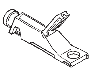
The radiator also has a drain cock located in the bottom of the left or right hand tank. The drain cock unit includes the drain cock and drain cock seal.
Heat is removed from the coolant as the coolant passes through the radiator. The fins on the core transfer heat from the coolant passing through the tubes. Air passing between the fins absorbs the heat and cools the coolant.
Pressure Cap
The pressure cap is a cap that seals and pressurizes the cooling system. It contains a blow off or pressure valve and a vacuum or atmospheric valve.
- The pressure valve is held against its seat by a spring and protects the radiator by relieving pressure if it exceeds 20 psi.
- The vacuum valve is held against its seat by a spring, which permits opening of the valve to relieve vacuum created in the cooling system as it cools off. The vacuum, if not relieved, could cause the radiator hoses to collapse.
The pressure cap allows pressure in the cooling system to build up. As the pressure builds, the boiling point of the coolant goes up as well. Therefore, the coolant can be safely run at a temperature higher than the boiling point of the coolant at atmospheric pressure. The hotter the coolant is, the faster the heat moves from the radiator to the cooler passing air.
However, if the pressure exceeds the strength of the spring, the pressure valve rises so that the excess pressure can escape.
When the engine cools down, the temperature of the coolant drops and a vacuum is created in the cooling system. This vacuum causes the vacuum valve to open, allowing outside air into the cooling system. This equalizes the pressure in the cooling system with atmospheric pressure, thus preventing the radiator hoses from collapsing.
Engine Coolant Bypass Valve {If Equipped}
The engine water outlet includes a engine coolant bypass valve, which opens at around 4, 000 RPM. All coolant is circulated through the heater core when the RPM is below 4, 000 while the engine thermostat is fully closed during engine warm up. The engine coolant bypass valve opens at around 4, 000 RPM and above, which stops increase of flow rate to the heater core and forces some portion of coolant through a heater bypass loop in order to protect the heater core from excessive coolant pressure. In rare cases, the engine coolant bypass valve may be stuck open, causing a lack of cabin heat.
Surge Tank
The surge tank is a plastic tank with a pressure cap mounted to it. The tank is mounted at a point higher than all other coolant passages. The surge tank provides an air space in the cooling system. The air space allows the coolant to expand and contract. The surge tank also provides a coolant fill point and a central air bleed location.
During vehicle use, the coolant heats and expands. The coolant that is displaced by this expansion flows into the surge tank. As the coolant circulates, air is allowed to exit. This is an advantage to the cooling system. Coolant without bubbles absorbs heat much better than coolant with bubbles.
Air Baffles and Seals
The cooling system uses deflectors, air baffles and air seals to increase cooling system capability.
Deflectors are installed under the vehicle to redirect airflow beneath the vehicle and through the radiator to increase engine cooling. Air baffles are also used to direct airflow through the radiator and increase cooling capability. Air seals prevent air from bypassing the radiator and A/C condenser, and prevent recirculation of hot air for better hot weather cooling and A/C condenser performance.
Water Pump
The water pump is a centrifugal vane impeller type pump. The pump consists of a housing with coolant inlet and outlet passages and an impeller. The impeller is a flat plate mounted on the pump shaft with a series of flat or curved blades or vanes. When the impeller rotates, the coolant between the vanes is thrown outward by centrifugal force. The impeller shaft is supported by one or more sealed bearings, which never need to be lubricated. With a sealed bearing, grease cannot leak out, and dirt and water cannot get in.
The water pump circulates coolant throughout the cooling system. The pump is driven by the crankshaft from the drive belt.
Thermostat
The thermostat is a coolant flow control component, whose purpose is to regulate the operating temperature of the engine. The thermostat utilizes a temperature sensitive wax-pellet element, which connects to a valve through a piston. Heating is causing the element to expand and exert pressure against a rubber diaphragm. This pressure forces the valve to open. Cooling causes the element to contract. This contraction allows a spring to push the valve closed.
When the coolant temperature is below 91ºC (195ºF), the thermostat valve remains closed. This prevents circulation of the coolant to the radiator and allows the engine to warm up quickly. After the coolant temperature reaches 91ºC (195ºF), the thermostat valve will open. The switch point will differ a little depending on engine. The coolant is then allowed to circulate through the thermostat to the radiator where the engine heat is dissipated to the atmosphere. The thermostat also provides a restriction in the cooling system, even after opening. This restriction creates a pressure difference which prevents cavitations at the water pump and forces coolant to circulate through the engine block.
For some engines a solenoid thermostat controlled by the ECM will open and close the circulation.
Transmission Oil Cooler
The transmission oil cooler is a heat exchanger and is located inside the right side end tank of the radiator.
The transmission fluid temperature is regulated by the temperature of the engine coolant that surrounds the oil cooler as the transmission fluid passes through the cooler.
The transmission oil pump circulates the fluid through the feed line to the oil cooler. The fluid then flows through the cooler while the engine coolant absorbs heat from the fluid. The fluid is then pumped through the return line to the transmission.
Special Tools and Equipment
SPECIAL TOOLS
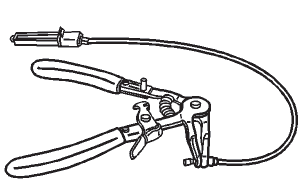
BO-38185
J-38185
Hose Clamp Pliers

GE-26568
J-26568
Coolant and Battery Fluid Tester
GE-42401- A
J-42401-A
Radiator Surge Tank and Pressure Cap Tester
GE-47622
Hose Clamp Pliers
READ NEXT:
 Firing Order and Cylinder Identification
NOTE: This information is intended as a quick reference for firing
order and
cylinder identification only. The information provided covers many
vehicles and may include some information that does not
SEE MORE:
TPMS Reset Procedures
NOTE: The TPMS sensor Relearn procedure must be performed after every
tire
rotation, BCM replacement, or sensor replacement.
When the tire pressure monitor system detects a significant loss, or gain of
tire pressure, the tire pressure
monitor indicator icon is illuminated on the instrument cluster
Interior Backlighting Malfunction
Diagnostic Instructions
Perform the Diagnostic System Check - Vehicle prior to using this
diagnostic procedure.
Review Strategy Based Diagnosis for an overview of the diagnostic
approach.
Diagnostic Procedure Instructions provides an overview of each
diagnostic category.
Diagnostic Fault
