Buick Regal: DTC P0722, P077C, or P077D
Diagnostic Instructions
- Perform the Diagnostic System Check prior to using this diagnostic procedure: Refer to Diagnostic System Check - Vehicle
- Review the description of Strategy Based Diagnosis:Strategy Based Diagnosis
- An overview of each diagnostic category can be found here: Refer to Diagnostic Procedure Instructions
DTC Descriptor
DTC P0722
Output Speed Sensor Circuit No Signal
DTC P077C
Output Speed Sensor Circuit Low Voltage
DTC P077D
Output Speed Sensor Circuit High Voltage
Diagnostic Fault Information
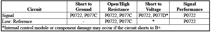
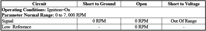
Typical Scan Tool Data
Transmission OSS
Circuit/System Description
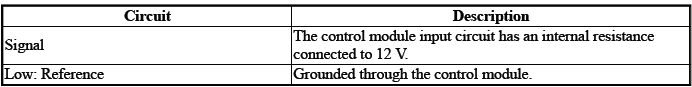
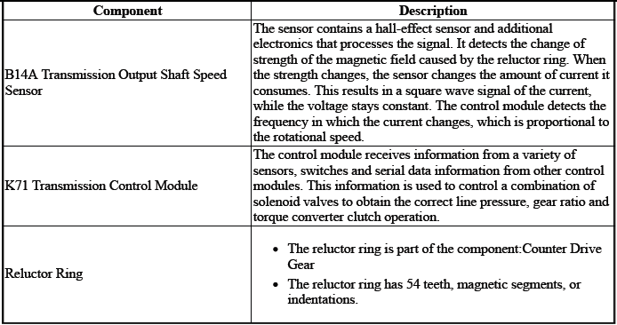
The sensor is an input to the control module K71. The input signal is used to determine the rotational speed of the component:Output Shaft The control module uses this data, along with other data, to adjust or control the following:
- Torque Converter Clutch
- Transmission Shifting
Conditions for Running the DTC
P0722
- DTC P077C, P077D, P07BF, P07C0, P0973, P0974, P0748, P0778, P0798,
P0962, P0963, P0967, P0970.
P0971, P2716, P2720, P2721, P2725, P2729, P2730, P2734, P2738, P2739 = Not set
- Engine Speed= Greater than 400 RPM
- Fail-Safe Mode=Inactive
- Ignition Voltage=10.2 to 15.5 V
- K71 Transmission Control Module= Communication Enabled
- Transmission Range=Drive
Frequency the DTC runs=Continuously - After the running conditions are met - For 2 s
P077C, P077D
- Engine Speed= Greater than 400 RPM
- Ignition Voltage=10.2 to 15.5 V
- K71 Transmission Control Module= Communication Enabled
Frequency the DTC runs=Continuously - After the running conditions are met - For 2 s
Conditions for Setting the DTC
P0722
Transmission OSS=0 RPM & Transmission ISS=Greater than 0 RPM
P077C
Transmission OSS=Invalid Signal Received - Short to Ground
P077D
Transmission OSS=Invalid Signal Received - Short to Voltage
Actions Taken When the DTC Sets
DTCs listed in the DTC Descriptor Category=Type A DTC
- Autostart/Autostop=Disabled - If equipped
- Fail-Safe Mode=Active
- { P077C, P077D }Transmission gear allowed=4th Gear - After a stop
- { P0722 }Transmission gear allowed=6th gear
- Transmission ISS=Calculated
Conditions for Clearing the DTC
DTCs listed in the DTC Descriptor Category=Type A DTC
Reference Information
Schematic: Reference
Refer to Automatic Transmission Controls Wiring Schematics
Connector End View: Reference
Refer to Component Connector End View Index
Component View: Reference
Refer to Disassembled Views
Description and Operation
Refer to Transmission General Description
Electrical Information: Reference
- Refer to Circuit Testing
- Refer to Connector Repairs
- Refer to Testing for Intermittent Conditions and Poor Connections
- Refer to Wiring Repairs
DTC Type: Reference
Refer to Powertrain Diagnostic Trouble Code (DTC) Type Definitions
Scan Tool: Reference
Refer to Control Module: References
Circuit/System Verification
1. Engine - Running.
2. Transmission - Park.
CAUTION: Support the lower control arms in the normal horizontal position in order to avoid damage to the drive axles. Do not operate the vehicle in gear with the wheels hanging down at full travel.
3. Raise and support the vehicle.
4. Transmission - Drive.
5. Verify the scan tool parameter:Transmission OSS=The value should change smoothly and gradually as the vehicle speed is increased and decreased.
- If the value does not change smoothly and gradually
Refer to Circuit/System Testing
- Go to next step: If the value does not change smoothly and gradually
6. Operate the vehicle within the Conditions for Running the DTC. You may also operate the vehicle within the conditions that you observed from the Freeze Frame/Failure Records data.
Verify the DTC does not set.
- If the DTC sets
Refer to Circuit/System Testing
- Go to next step: If the DTC is not set
7. All OK.
Circuit/System Testing
NOTE: It may take up to 2 min for all vehicle systems to power down before an accurate ground or low reference circuit continuity test can be performed.
1. Ignition/Vehicle & All vehicle systems - Off.
2. Remove the component:K71 Transmission Control Module.
NOTE: Twisting or tilting of the transmission control module electrical connector while disconnecting may result in bent or misaligned electrical terminal pins.
3. Test for 4500000 to 5000000 ohms between the test points:Signal circuit terminal 11 & Low: Reference circuit terminal 20
- If not between 4500000 and 5000000 ohms
- Remove the component:Control Valve Body Cover
- Disconnect the electrical connector:B14C Transmission Input Shaft Speed Sensor
- Test for less than 2 ohms between the test points:
- Control circuit terminal 2@Component harness & Signal circuit terminal 11@Control module harness
- Low: Reference circuit terminal 1@Component harness & Low: Reference circuit terminal 20@Control module harness
- If 2 ohms or greater - Replace the component:Automatic Transmission Wiring Harness
- If less than 2 ohms - Replace the component:B14C Transmission Input Shaft Speed Sensor
- Go to next step: If between 4500000 and 5000000 ohms
4. Test for infinite resistance between the test points:
- Signal circuit terminal 11 & Transmission Case
- Low: Reference circuit terminal 20 & Transmission Case
- If less than infinite resistance
- Remove the component:Control Valve Body Cover
- Disconnect the electrical connector:B14C Transmission Input Shaft Speed Sensor
- Test for infinite resistance between the test points:
- Signal circuit terminal 2@Component harness & Transmission Case
- Low: Reference circuit terminal 1@Component harness & Transmission Case
- If less than infinite resistance - Replace the component:Automatic Transmission Wiring Harness
- If less than infinite resistance - Replace the component:B14A Transmission Output Shaft Speed Sensor
- Go to next step: If infinite resistance
- Go to next step: If infinite resistance
5. Replace the component:K71 Transmission Control Module
Component Testing
1. Ignition/Vehicle - Off.
2. Disconnect the electrical connector:B14A Transmission Output Shaft Speed Sensor.
NOTE: The component's temperature should be 19 to 21ºC (66 to 70ºF) while testing.
3. Test for 4500000 to 5000000 ohms between the test points:Control terminal 2 & Low: Reference terminal 1.
- If not between 4500000 and 5000000 ohms
Replace the component:B14A Transmission Output Shaft Speed Sensor
- Go to next step: If between 4500000 and 5000000 ohms
4. Test for infinite resistance between the test points:Each terminal of the component & The component's housing.
- If less than infinite resistance
Replace the component:B14A Transmission Output Shaft Speed Sensor
- Go to next step: If infinite resistance
5. All OK.
Repair Instructions
Perform the Diagnostic Repair Verification after completing the repair: Refer to Diagnostic Repair Verification
- Refer to Control Valve Body Replacement
- Refer to Counter Drive Gear Removal - B14A Transmission Output Shaft Speed Sensor
- Refer to Counter Drive Gear Installation - B14A Transmission Output Shaft Speed Sensor
- Refer to Wiring Harness Wire Replacement - Automatic Transmission Wiring Harness
- For control module replacement, programming, and setup: Refer to Control Module: References
READ NEXT:
 DTC P0729-P0735, P076F, or P07D9
Diagnostic Instructions
Perform the Diagnostic System Check prior to using this diagnostic
procedure: Refer to Diagnostic System
Check - Vehicle
Review the description of Strategy Based Diagnosi
DTC P0741 or P0742
Diagnostic Instructions
Perform the Diagnostic System Check prior to using this diagnostic
procedure: Refer to Diagnostic System
Check - Vehicle
Review the description of Strategy Based Diagnosi
DTC P0748, P0962, or P0963
Diagnostic Instructions
Perform the Diagnostic System Check prior to using this diagnostic
procedure: Refer to Diagnostic System
Check - Vehicle
Review the description of Strategy Based Diagnosi
SEE MORE:
Auxiliary Audio Input Malfunction (IOR/IOS/IOT)
Diagnostic Instructions
Perform the Diagnostic System Check - Vehicle prior to using this
diagnostic procedure.
Review Strategy Based Diagnosis for an overview of the diagnostic
approach.
Refer to Diagnostic Procedure Instructions for an overview of each
diagnostic category.
DTC Descripto
Compact Spare Tire
Warning:
Driving with more than one
compact spare tire at a time could
result in loss of braking and
handling. This could lead to a
crash and you or others could be
injured. Use only one compact
spare tire at a time.
If this vehicle has a compact spare
tire, it was fully inflated when new;
however,
