Buick Regal: DTC P0717, P07BF, or P07C0
Diagnostic Instructions
- Perform the Diagnostic System Check prior to using this diagnostic procedure: Refer to Diagnostic System Check - Vehicle
- Review the description of Strategy Based Diagnosis: Strategy Based Diagnosis
- An overview of each diagnostic category can be found here: Refer to Diagnostic Procedure Instructions
DTC Descriptor
DTC P0717
Input Speed Sensor Circuit No Signal
DTC P07BF
Input Speed Sensor Circuit Low Voltage
DTC P07C0
Input Speed Sensor Circuit High Voltage
Diagnostic Fault Information
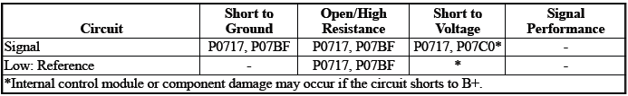
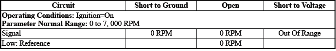
Typical Scan Tool Data
Transmission ISS
Circuit/System Description
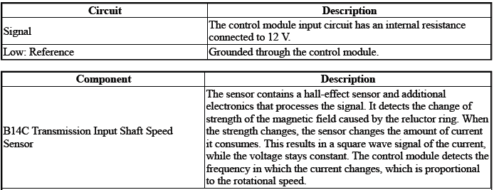
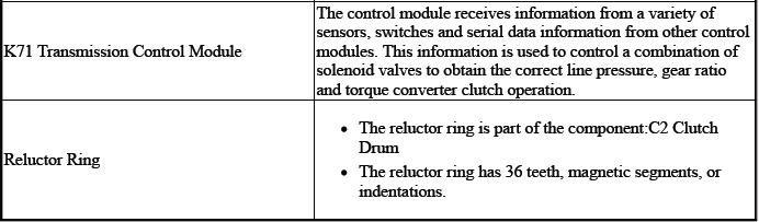
The sensor is an input to the control module K71. The input signal is used to determine the rotational speed of the component: Input Shaft
The control module uses this data, along with other data, to adjust or control the following:
- Torque Converter Clutch
- Transmission Shifting
Conditions for Running the DTC
P07BF, P07C0
- Ignition Voltage=10.2 to 15.5 V
- K71 Transmission Control Module= Communication Enabled
Frequency the DTC runs=Continuously - After the running conditions are met - For 2 s
Conditions for Setting the DTC
P0717
Transmission ISS=0 RPM & Transmission OSS=Greater than 0 RPM
P07BF
Transmission ISS=Invalid Signal Received - Short to Ground
P07C0
Transmission ISS=Invalid Signal Received - Short to Voltage
Actions Taken When the DTC Sets
DTCs listed in the DTC Descriptor Category=Type A DTC
- Autostart/Autostop=Disabled - If equipped
- Fail-Safe Mode=Active
- Learning=Disabled
- Torque Converter Clutch=Disabled
- Transmission OSS=Calculated
Conditions for Clearing the DTC
DTCs listed in the DTC Descriptor Category=Type A DTC
Reference Information
Schematic: Reference
Refer to Automatic Transmission Controls Wiring Schematics
Connector End View: Reference
Refer to Component Connector End View Index
Component View: Reference
Refer to Disassembled Views
Description and Operation
Refer to Transmission General Description
Electrical Information: Reference
- Refer to Circuit Testing
- Refer to Connector Repairs
- Refer to Testing for Intermittent Conditions and Poor Connections
- Refer to Wiring Repairs
DTC Type: Reference
Refer to Powertrain Diagnostic Trouble Code (DTC) Type Definitions
Scan Tool: Reference
Refer to Control Module: References
Circuit/System Verification
1. Engine - Running.
2. Transmission - Park.
3. Verify the scan tool parameter: Transmission ISS=Engine Speed.
- If not the specified state
Refer to Circuit/System Testing
- Go to next step: If the specified state
4. Transmission - Reverse.
5. Verify the scan tool parameter: Transmission ISS= 0.
- If not the specified state
Refer to Circuit/System Testing
- Go to next step: If the specified state
6. Operate the vehicle within the Conditions for Running the DTC. You may also operate the vehicle within the conditions that you observed from the Freeze Frame/Failure Records data.
Verify the DTC does not set.
- If the DTC sets
Refer to Circuit/System Testing
- Go to next step: If the DTC is not set
7. All OK.
Circuit/System Testing
NOTE: It may take up to 2 min for all vehicle systems to power down before an accurate ground or low reference circuit continuity test can be performed.
1. Ignition/Vehicle & All vehicle systems - Off
2. Remove the component:K71 Transmission Control Module
NOTE: Twisting or tilting of the transmission control module electrical connector while disconnecting may result in bent or misaligned electrical terminal pins.
3. Test for 4500000 to 5000000 ohms between the test points:Signal circuit terminal 18 & Low: Reference circuit terminal 17
- If not between 4500000 and 5000000 ohms
- Remove the component:Control Valve Body Cover
- Disconnect the electrical connector:B14C Transmission Input Shaft Speed Sensor
- Test for less than 2 ohms between the test points:
- Control circuit terminal 2@Component harness & Signal circuit terminal 18@Control module harness
- Low: Reference circuit terminal 1@Component harness & Low: Reference circuit terminal 17@Control module harness
- If 2 ohms or greater - Replace the component:Automatic Transmission Wiring Harness
- If less than 2 ohms - Replace the component:B14C Transmission Input Shaft Speed Sensor
- Go to next step: If between 4500000 and 5000000 ohms
4. Test for infinite resistance between the test points:
- Signal circuit terminal 18 & Transmission Case
- Low: Reference circuit terminal 17 & Transmission Case
- If less than infinite resistance
- Remove the component: Control Valve Body Cover
- Disconnect the electrical connector:B14C Transmission Input Shaft Speed Sensor
- Test for infinite resistance between the test points:
- Signal circuit terminal 2@Component harness & Transmission Case
- Low: Reference circuit terminal 1@Component harness & Transmission Case
- If less than infinite resistance - Replace the component: Automatic
Transmission Wiring Harness.
If less than infinite resistance - Replace the component:B14C Transmission Input Shaft Speed Sensor.
- Go to next step: If infinite resistance
5. Replace the component:K71 Transmission Control Module
Component Testing
1. Ignition/Vehicle - Off.
2. Disconnect the electrical connector:B14C Transmission Input Shaft Speed Sensor.
NOTE: The component's temperature should be 19 to 21ºC (66 to 70ºF) while testing.
3. Test for 4500000 to 5000000 ohms between the test points: Control terminal 2 & Low: Reference terminal 1.
- If not between 4500000 and 5000000 ohms
Replace the component:B14C Transmission Input Shaft Speed Sensor
- Go to next step: If between 4500000 and 5000000 ohms
4. Test for infinite resistance between the test points:Each terminal of the component & The component's housing.
- If less than infinite resistance
Replace the component:B14C Transmission Input Shaft Speed Sensor
- Go to next step: If infinite resistance
5. All OK.
Repair Instructions
Perform the Diagnostic Repair Verification after completing the repair: Refer to Diagnostic Repair Verification
- Refer to Control Valve Body Replacement
- Refer to Input Speed Sensor Replacement
- Refer to Wiring Harness Wire Replacement - Automatic Transmission Wiring Harness
- For control module replacement, programming, and setup: Refer to Control Module: References
READ NEXT:
 DTC P0722, P077C, or P077D
Diagnostic Instructions
Perform the Diagnostic System Check prior to using this diagnostic
procedure: Refer to Diagnostic System
Check - Vehicle
Review the description of Strategy Based Diagnosi
DTC P0729-P0735, P076F, or P07D9
Diagnostic Instructions
Perform the Diagnostic System Check prior to using this diagnostic
procedure: Refer to Diagnostic System
Check - Vehicle
Review the description of Strategy Based Diagnosi
DTC P0741 or P0742
Diagnostic Instructions
Perform the Diagnostic System Check prior to using this diagnostic
procedure: Refer to Diagnostic System
Check - Vehicle
Review the description of Strategy Based Diagnosi
SEE MORE:
Repair Instructions
Tire Pressure Indicator Sensor Replacement
Removal Procedure
1. Raise and suitably support the vehicle. Refer to Lifting and Jacking the
Vehicle.
2. Remove the tire and wheel assembly.
3. Dismount the tire from the rim.
4.
NOTE: Never fit the tire pressure indicator sensor on unapproved wheel
r
Cylinder Head Replacement
* PLEASE READ THIS FIRST *
NOTE: Examples used in this article are general in nature and do not
necessarily
relate to a specific engine or system. Illustrations and procedures have
been chosen to guide mechanic through engine overhaul process.
Descriptions of processes of cleaning, inspection, ass
