Buick Regal: Electronic Component Description
Control Module
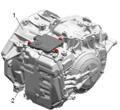
K71 Transmission Control Module
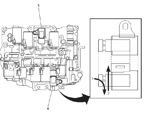
The TCM (2) is mounted directly on top of the transmission (1). The selector lever and transmission range sensor is integrated in the control module. The TCM is mounted so that the selector lever shaft goes through the control module. The selector lever position is calibrated with a scan tool, there is no mechanical adjustment.
An external 16-terminal connector connects to the vehicle's electrical system. Underneath the control module is another connector (33-terminal) that connects directly to the transmission. The TCM makes contact with all the transmission solenoids and sensors here.
NOTE: Magnetic fields from e.g. magnets and from high-current cables, such as starter cables and cables to auxiliary equipment, can interfere with the gear position sensor. A rule of thumb is max 1A per mm in distance from the control module. A starter cable carrying a current of 200A must therefore be kept at least 20 cm away from the control module.
The TCM has a microprocessor with clock, RAM memory and a programmable ROM. An internal bus connects the processor and memory with the I/O unit. The I/O unit reads values from the A/D converter for analogue inputs, digital inputs and bus, as well as activates the transistors' output stages.
Adaptive values are saved in a non-volatile memory (ROM). When changing the transmission, these values must be zeroed using scan tool. The values are will be zeroed automatically after replacing the control module using the scan tool.
B182 Gear Shift Position Sensor
A non-contact type shift position sensor is integrated in the TCM. The sensor detects shift position by using a hall effect sensor, which outputs specified voltage according to the shift position (P, R, N, D). The magnet position in the sensor changes when moving the shift lever, enabling the hall effect sensor to convert magnetic field strength into an electrical signal according to the shift position.
B81 Park/Neutral Position Switch
The park/neutral position (PNP) switch is part of the K71 Transmission Control Module (TCM) assembly. The TCM provides a ground to the K20 Engine Control Module in park and neutral. The K20 ECM sends a 12V trace on the PNP circuit to the K71 TCM, used for circuit diagnostics. The PNP provides a range signal (permission to crank) to the ECM to enable engine start.
Pressure Control Solenoid Valves - Shifting
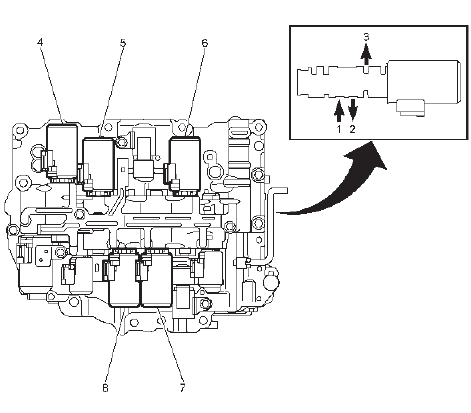
- In
- Out
- Exhaust
- Q27E Pressure Control Solenoid Valve 5
- Q27D Pressure Control Solenoid Valve 4
- Q27A Pressure Control Solenoid Valve 1
- Q27B Pressure Control Solenoid Valve 2
- Q27C Pressure Control Solenoid Valve 3
Q27A Pressure Control Solenoid Valve 1
The PWM controlled solenoid valve is mounted in the transmission valve housing and controls the pressure in C1.
The valve is active in shift position D - (gears 1, 2, 3, 4 and 5).
The control module activates the valve by pulsing it with B+ (300 Hz PWM). The current varies between 100-1100 mA. The solenoid is normally closed and the hydraulic pressure decreases as the current increases.
Q27B Pressure Control Solenoid Valve 2
The PWM controlled solenoid valve is mounted in the transmission valve housing and controls the pressure in C2.
The valve is active in shift position D - (gears 5, 6, 7, 8).
The control module activates the valve by pulsing it with B+ (300 Hz PWM). The current varies between 100-1100 mA. The solenoid is normally closed and the hydraulic pressure decreases as the current increases.
Q27C Pressure Control Solenoid Valve 3
The PWM controlled solenoid valve is mounted in the transmission valve housing and controls the pressure in C3.
The valve is active in shift position P, R, N, D - (gears 3 and 7).
The control module activates the valve by pulsing it with B+ (300 Hz PWM). The current varies between 100-1100 mA. The solenoid is normally closed and the hydraulic pressure decreases as the current increases.
Q27D Pressure Control Solenoid Valve 4
The PWM controlled solenoid valve is mounted in the transmission valve housing and controls the pressure in clutch C4. The valve is active in shift position D - (gears 4 and 6).
The control module activates the valve by pulsing it with B+ (300 Hz PWM). The current varies between 100-11000 mA. The solenoid is normally closed and the hydraulic pressure decreases as the current increases.
Q27E Pressure Control Solenoid Valve 5
The PWM controlled solenoid valve is mounted in the transmission valve housing and controls the pressure in C5.
The valve is active in shift position D - (gears 2 and 8).
The control module activates the valve by pulsing it with B+ (300 Hz PWM). The current varies between 100-1100 mA. The solenoid is normally closed and the hydraulic pressure decreases as the current increases.
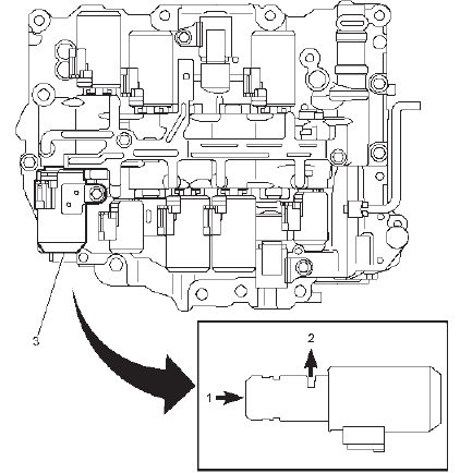
Pressure Control Solenoid Valve - Non-Shifting
- In
- Out
- Exhaust
- Q23 Line Pressure Control Solenoid Valve
- Q39A Torque Converter Clutch Pressure Control Solenoid Valve
Q23 Line Pressure Control Solenoid Valve - Pressure Control Solenoid Valve 6
The PWM controlled solenoid valve is mounted in the transmission valve housing and controls the transmission line pressure
The control module activates the valve by pulsing it with B+ (300 Hz PWM). The current varies between 100-1100 mA. The solenoid is normally open and the hydraulic pressure increases as the current increases.
Q39A Torque Converter Clutch Pressure Control Solenoid Valve
The solenoid valve is mounted in the transmission valve housing and controls the pressure for the torque converter clutch The pressure is modulated so that full, partial or no engagement is achieved.
The control module activates the valve by pulsing it with B+ (300 Hz PWM). The current varies between 100-1100 mA. The solenoid is normally closed and the hydraulic pressure increases the current increases.
Q27G Pressure Control Solenoid Valve 7 { If equipped }
Q27G Pressure Control Solenoid Valve 7 { If equipped }
The normally closed solenoid valve is mounted in the transmission valve housing and is used to engage the C1 clutch during an autostop event.
The control module activates the valve by applying B+.
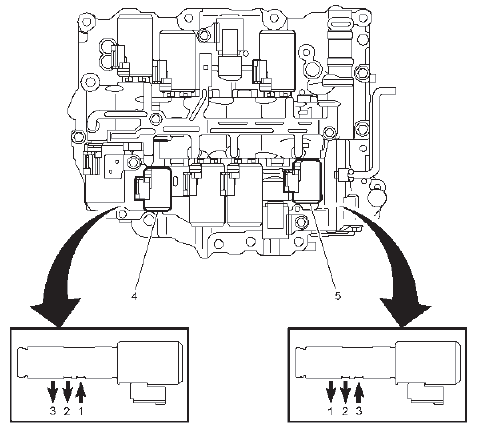
Shift Solenoids
- On
- Off
- Q32A Shift Solenoid Valve 1
- Q32B Shift Solenoid Valve 2
Q32A Shift Solenoid Valve 1 & Q32B Shift Solenoid Valve 2
The normally closed solenoid valves are mounted in the transmission valve housing and are turned on and off by the TCM. Activating these components will cause 1st gear engine braking or a gear shift, depending on the state of the other solenoids within the transmission.
The control module activates the valves by applying B+. The solenoid is grounded through its housing
Speed Sensors
- Counter Drive Gear & B14A Transmission Output Shaft Speed Sensor
- C2 Clutch Drum & B14C Transmission Input Shaft Speed Sensor
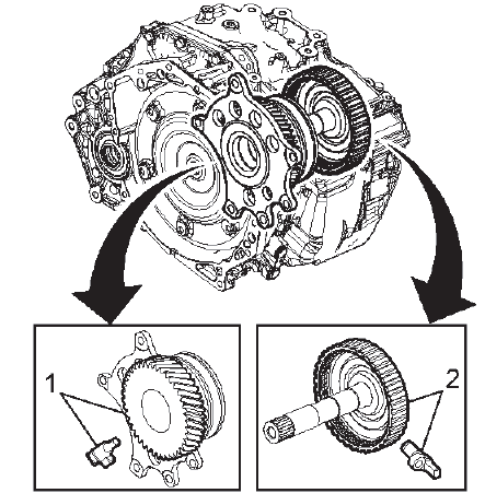
B14A Transmission Output Shaft Speed Sensor
The sensor is mounted inside the valve housing in the rear part of the transmission and measures the transmission output shaft speed. This value is used by TCM to determine gear change points and vehicle speed. The sensor contains a hall-effect sensor and additional electronics that processes the signal. It detects the change of strength of the magnetic field caused by the reluctor ring. When the strength changes, the sensor changes the amount of current it consumes. This results in a square wave signal of the current, while the voltage stays constant. The control module detects the frequency in which the current changes, which is proportional to the rotational speed. The 2 - wire hall effect sensor faces the counter drive gear, there are 56 teeth on the gear.
B14C Transmission Input Shaft Speed Sensor
The sensor is mounted inside the valve housing in the front part of the transmission and measures the speed of the transmission input shaft. This value is used by the TCM to calculate the actual gear change time and to regulate lock up. The sensor contains a hall-effect sensor and additional electronics that processes the signal. It detects the change of strength of the magnetic field caused by the reluctor ring. When the strength changes, the sensor changes the amount of current it consumes. This results in a square wave signal of the current, while the voltage stays constant.
The control module detects the frequency in which the current changes, which is proportional to the rotational speed.
The 2 - wire hall effect sensor faces the indentations on the C2 clutch drum, there are 36 indentations on the drum.
Temperature Sensor
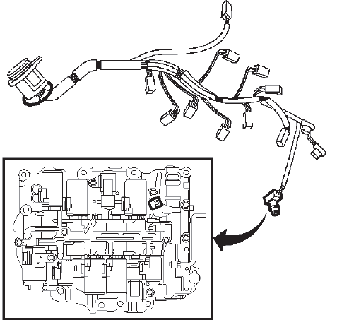
B13 Transmission Fluid Temperature Sensor
The temperature sensor is mounted in the transmission valve housing and informs the control module about the current temperature. The value is used to correct the PWM ratio to the solenoids so that the gear changes are not affected by the viscosity of the oil. It is also used to activate the special gear change program in case of overheating.
The sensor comprises an NTC resistor built into a plastic casing. The NTC resistor characteristic means that the resistance drops as the temperature rises. The NTC resistor is supplied with 5V through a pull up from control module.
READ NEXT:
 Special Tools and Equipment
SPECIAL TOOLS
DT-26941
J-26941
Remover
DT-37228
J-37228
Seal Cutter
DT-43911
J-43911
Selector Shaft Seal
Remover
DT-44215
J-44215
Rear Seal Installer
DT-44809
J-44809
Output Shaft Seal
Installer
Specifications
FASTENER SPECIFICATIONS
Single Use Non-Threaded Fasteners/Components
NOTE:
All fasteners/components listed in this table MUST BE DISCARDED and replaced
with NEW
after removal.
Application
Power Trans
SEE MORE:
DTC P16D7-P16D9
Diagnostic Instructions
Perform the Diagnostic System Check - Vehicle prior to using this
diagnostic procedure.
Review Strategy Based Diagnosis for an overview of the diagnostic
approach.
Diagnostic Procedure Instructions provides an overview of each
diagnostic category.
DTC Descriptors
D
Rear Suspension 4 Corner Air Leveling Position Sensor Replacement (CNQ)
Removal Procedure
1. Remove the rear tire and wheel assembly.
2. Separate the rear suspension 4 corner air leveling position sensor harness
clip from the underbody
rear side rail.
3. Electrical Connector@Rear Suspension 4 Corner Air Leveling Position Sensor -
Disconnect.
4.
Link Rod (1)@Ball
