Buick Regal: Line Pressure Check
Special Tools
- EN-21867 Pressure Gauge
- EN-21867-50 Transmission Line Pressure Adapter
For equivalent regional tools, refer to Special Tools.
Line Pressure

1. Apply the parking brake and chock the wheels.
2. Install an SLT current measuring machine.
If the machine is not available, installation is not required.
3.
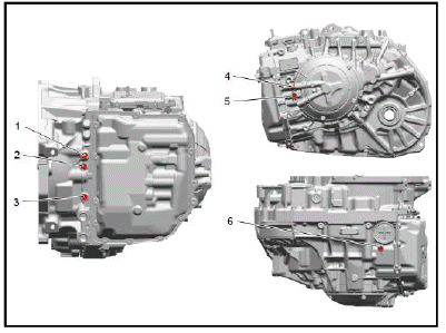
Disconnect the test plug (1) and install EN-21867 Pressure Gauge with EN-21867-50 adapter.
4. Start engine and shift to the "D" position then check oil pressure at idling engine speed.
5. Having completed steps 1 through 4, and with the brake pedal not depressed, line pressure at engine idle should fall within the range specified above.
6.
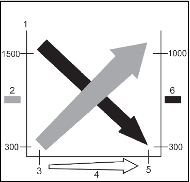
For the second portion of the line pressure check, firmly depress the brake pedal and perform three stall tests while monitoring the line pressure. Smoothly depress the accelerator pedal to progress from 0 to 100% for 5 seconds. Average the results of the 3 tests. Results should approximate values shown in the chart above.
- Drive Range
- Oil Pressure [kpa]
- Idle
- Throttle Opening
- Stall
- SLT current [mA]
NOTE:
- Stall testing causes a sudden rise in the automatic transmission fluid temperature (ATF). Do not continue each test for more than 5 seconds per test. Do not perform more than 3 times without allowing the transmission to cool.
- Line Pressure is actively controlled via the transmission control module (TCM). Some deviation from the chart above can be normal. It is important to perform the test 3 times and average the tests.
ROAD TEST
The purpose of the road test is to accurately grasp symptoms of the malfunction and to check completion after the repair is finished.
Be sure to perform the road test under the conditions below:
- Only when traffic conditions permit
- After engine inspection and adjustment.
- With ATF temperature 50-80ºC (122-176ºF) under ordinary driving conditions
- A/C, lights, etc., are turned OFF
- Cruise control is OFF
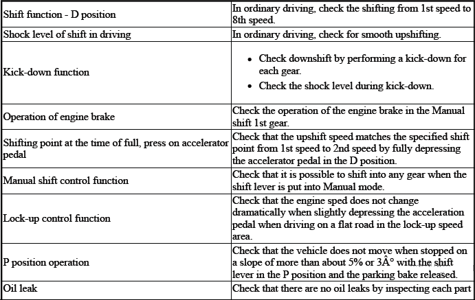
Perform the road test referring to the table below.
Road Test
TORQUE CONVERTER DIAGNOSIS
The torque converter clutch (TCC) is applied by fluid pressure, which is controlled by a pulse width modulated (PWM) solenoid valve. This solenoid valve is located inside of the automatic transmission assembly. The solenoid valve is controlled through a combination of computer controlled switches and sensors.
Torque Converter Stator
The torque converter stator roller clutch can have two different malfunctions.
- The stator assembly freewheels in both directions.
- The stator assembly remains locked up at all times.
Poor Acceleration at Low Speed
If the stator is freewheeling at all times, the car tends to have poor acceleration from a standstill. At speeds above 50 - 55 km/h (30 - 35 mph), the car may act normally. For poor acceleration, you should first determine that the exhaust system is not blocked, and the transmission is in First gear when starting out.
If the engine freely accelerates to high RPM in NEUTRAL, you can assume that the engine and the exhaust system are normal. Check for poor performance in DRIVE and REVERSE to help determine if the stator is freewheeling at all times.
Poor Acceleration at High Speed
If the stator is locked up at all times, performance is normal when accelerating from a standstill. Engine RPM and car speed are limited or restricted at high speeds. Visual examination of the converter may reveal a blue color from overheating.
If the converter has been removed, you can check the stator roller clutch by inserting a finger into the splined inner race of the roller clutch and trying to turn the race in both directions. You should be able to freely turn the inner race clockwise, but you should have difficulty in moving the inner race counterclockwise or you may be unable to move the race at all.
Noise
NOTE: Do not confuse this noise with pump whine noise, which is usually noticeable in PARK, NEUTRAL and all other gear ranges. Pump whine will vary with line pressure.
You may notice a torque converter whine when the vehicle is stopped and the transmission is in DRIVE or REVERSE. This noise will increase as you increase the engine RPM. The noise will stop when the vehicle is moving or when you apply the torque converter clutch, because both halves of the converter are turning at the same speed.
Perform a stall test to make sure the noise is actually coming from the converter:
1. Place your foot on the brake.
2. Put the gear selector in DRIVE.
3. Depress the accelerator to approximately 1, 200 RPM for no more than 6 seconds.
CAUTION: You may damage the transmission if you depress the accelerator for more than 6 seconds.
A torque converter noise will increase under this load.
Torque Converter Clutch Shudder
The key to diagnosing TCC shudder is to note when it happens and under what conditions.
TCC shudder which is caused by the transmission should only occur during the apply or the release of the converter clutch. Shudder should never occur after the TCC plate is fully applied.
If the shudder occurs while the TCC is applying, the problem can be within the transmission or the torque converter.
Something is causing one of the following conditions to occur:
- Something is not allowing the clutch to become fully engaged.
- Something is not allowing the clutch to release.
- The clutch is releasing and applying at the same time.
One of the following conditions may be causing the problem to occur:
- Leaking turbine shaft seals
- A restricted release orifice
- A distorted clutch or housing surface due to long converter bolts
- Defective friction material on the TCC plate
If Shudder Occurs After TCC has Applied
If shudder occurs after the TCC has applied, most of the time there is nothing wrong with the transmission.
As mentioned above, the TCC is not likely to slip after the TCC has been applied. Engine problems may go unnoticed under light throttle and load, but they become noticeable after the TCC apply when going up a hill or accelerating. This is due to the mechanical coupling between the engine and the transmission.
Once TCC is applied, there is no torque converter, fluid coupling, assistance. Engine or driveline vibrations could be unnoticeable before TCC engagement.
Inspect the following components in order to avoid misdiagnosis of TCC shudder. An inspection will also avoid the unnecessary disassembly of a transmission or the unnecessary replacement of a torque converter.
- Spark plugs - Inspect for cracks, high resistance or a broken insulator.
- Coil - Look for a black discoloration on the bottom of the coil. This indicates arcing while the engine is misfiring.
- Fuel injector - The filter may be plugged.
- Vacuum leak - The engine will not get a correct amount of fuel. The mixture may run rich or lean depending on where the leak occurs.
- EGR valve (Petrol) - The valve may let in too much or too little unburnable exhaust gas and could cause the engine to run rich or lean.
- MAP sensor - Like a vacuum leak, the engine will not get the correct amount of fuel for proper engine operation.
- Carbon on the intake valves - Carbon restricts the proper flow of air/fuel mixture into the cylinders.
- Flat cam - Valves do not open enough to let the proper fuel/air mixture into the cylinders.
- Oxygen sensor - This sensor may command the engine too rich or too lean for too long.
- Fuel pressure - This may be too low.
- Engine mounts - Vibration of the mounts can be multiplied by TCC engagement.
- Axle joints - Check for vibration.
- TP Sensor (Petrol) - The TCC apply and release depends on the TP Sensor in many engines. If the TP Sensor is out of specification, TCC may remain applied during initial engine loading.
- Cylinder balance - Bad piston rings or poorly sealing valves can cause low power in a cylinder.
- Fuel contamination - This causes poor engine performance.
Torque Converter Evaluation and Diagnosis
Replace the torque converter if any of the following conditions exist:
- External leaks appear in the hub weld area.
- The converter hub is scored or damaged.
- The converter pilot is broken, damaged, or fits poorly into the crankshaft.
- You discover steel particles after flushing the cooler and the cooler lines.
- The pump is damaged, or you discover steel particles in the converter.
- The vehicle has TCC shudder and/or no TCC apply. Replace the torque converter only after all hydraulic and electrical diagnoses have been made. The converter clutch material may be glazed.
- The converter has an imbalance which cannot be corrected.
- The converter is contaminated with engine coolant which contains antifreeze.
- An internal failure occurs in the stator roller clutch.
- You notice excessive end play.
- Overheating produces heavy debris in the clutch.
- You discover steel particles or clutch lining material in the fluid filter or on the magnet, when no internal parts in the unit are worn or damaged. This condition indicates that lining material came from the converter.
Do not replace the torque converter if you discover any of the following symptoms:
- The oil has an odor or the oil is discolored, even though metal or clutch facing particles are not present.
- The threads in one or more of the converter bolt holds are damaged. Correct the condition with a new thread inset.
- Transmission failure did not display evidence of damaged or worn
internal parts, steel particles or clutch plate
lining material in the unit and inside the fluid filter.
- If the vehicle has been exposed to high mileage only. An exception may exist where the lining of the torque converter clutch dampener plate has seen excess wear by vehicles operated in heavy and/or constant traffic, such as taxi, delivery, or police use.
NOISE AND VIBRATION ANALYSIS
Idling
- Engine Malfunction
- Engine to Transmission Mounting
- Exhaust Pipe Resonance
- Drivetrain
- Suspension
- ATF Level/Condition
Garage Shift
- Engine Malfunction
- Engine to Transmission Mounting
- Exhaust Pipe Resonance
- Drivetrain
- Suspension
- Tire/Wheel Imbalance
- ATF Level/Condition
Driving
- Engine Malfunction
- Engine to Transmission Mounting
- Exhaust Pipe Resonance
- Drivetrain
- Suspension
- Tire/Wheel Imbalance
- ATF Level/Condition
Up Shift and/or Down Shift
- Engine Malfunction
- Engine to Transmission Mounting
- Exhaust Pipe Resonance
- Drivetrain
- Suspension
- ATF Level/Condition
ENGINE COOLANT/WATER IN TRANSMISSION
CAUTION: The antifreeze or water will deteriorate the seals, gaskets and the glue that bonds the clutch material to the pressure plate. Both conditions may cause damage to the transmission.
If antifreeze or water has entered the transmission, perform the following:
1. Replace all of the rubber type seals. The coolant will attack the seal material which will cause leakage.
2. Replace the torque converter.
3. Flush the cooler lines after the transmission cooler has been properly repaired or replaced.
READ NEXT:
 Fluid Leak Diagnosis
General Method
1. Verify that the leak is transmission fluid.
2. Thoroughly clean the suspected leak area.
3. Operate the vehicle for 24 km (15 mi), or until normal operating temperatures
are reach
Harsh Garage Shift
"N" to "D"
ATF Level/Condition
TCM
Shift Cable Adjustment
Valve Body
"N" to "R"
ATF Level/Condition
TCM
Shift Cable Adjustment
Valve Body
ERRATIC SHIFT
Erratic Shifting
Output Speed Sens
SEE MORE:
Exterior Lighting Systems Description and Operation
Exterior Lamps
The exterior lighting system consist of the following lamps:
Adaptive forward lighting
Automatic headlamp leveling
Automatic high beam assist
Backup lamps
Daytime running lamps
Exterior courtesy lamps
Front fog lamps
Hazard warning lamps
Headlamps
Park, tail, license and ma
Turbocharger Removal (1ST Design Tamper-Proof PCV System)
1.
NOTE: In the event that a bolt breaks upon removal of components,
perform an
extraction of the broken bolt.
Remove the turbocharger heat shield bolts (1, 3).
2. Remove the turbocharger heat shield (2).
3.
Remove the turbocharger wastegate actuator arm retainer (3).
4. Remove the turbocharger
