Buick Regal: Lock Cylinder Coding - Ignition
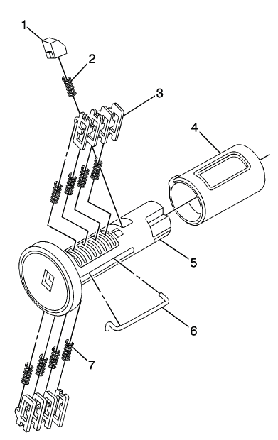
The ignition lock cylinder uses 8 key cut positions, 1 - 8. The ignition cylinder tumblers (3) are located on alternate sides of the cylinder (5). They are not snap-in and are not self-retaining. It follows the key code with the first tumbler being the first depth of the key code, closest to the head of the key.
NOTE: All lock cylinders for side milled keys have right and left tumblers.
The location of the tooth of the tumbler determines whether it is right of left. Illustrations in this procedure show the right tumblers on the top and the left tumblers on the bottom. All tumblers are marked 1R, 1L, 2R, or 2L. The number being cut depth and the letter meaning right or left.
1. Hold the ignition cylinder assembly (5) so the side with the tumbler spring pocket located closest to the head of the cylinder is facing up.
2. Insert the tumbler spring (7) into each of the 4 spring pockets of the cylinder assembly. This side of the cylinder used left tumblers.
3. The first tumbler (3) to be loaded will be the first key cut position, which is the first number in the key code. Install the tumbler in the slot over the spring. Install the remaining tumblers following the key code and same process, pressing the tumblers in place until they are secure.
4. Rotate the cylinder assembly. Insert the tumbler spring into each of the spring pockets of the cylinder assembly. This side of the cylinder used right tumblers.
5. The first tumbler (3) to be loaded will be the second key cut position, the second number in the key code. Install the first tumbler in the slot over the spring. Install the remaining tumblers following the key code and same process, pressing the tumblers in place until they are secure.
6. Inspect for correct loading of the tumblers by inserting the key into the cylinder. All tumblers should drop flush with the lock cylinder body diameter.
7. With the key in the cylinder assembly insert the round connector (6), insert the retainer spring (2) in the retainer slot located in the cylinder assembly. Insert the retainer (1) lining it up in the slot over the spring. Depress the retainer and hold.
8. Insert the cylinder into the sleeve (4) as shown in the print. Make sure the actuator stays located properly in the cylinder.
9. When the key is removed, the lock should stay together.
10. Lightly lubricate the outside surface in the tumbler area of in the lock body and down the key slot using the provided grease. Insert and extract the key 5 times to lubricate the keyway.
11. Insert the key and function the lock 3 times to distribute the grease inside the sleeve.
12. Verify the key position for inserting the lock into the column.
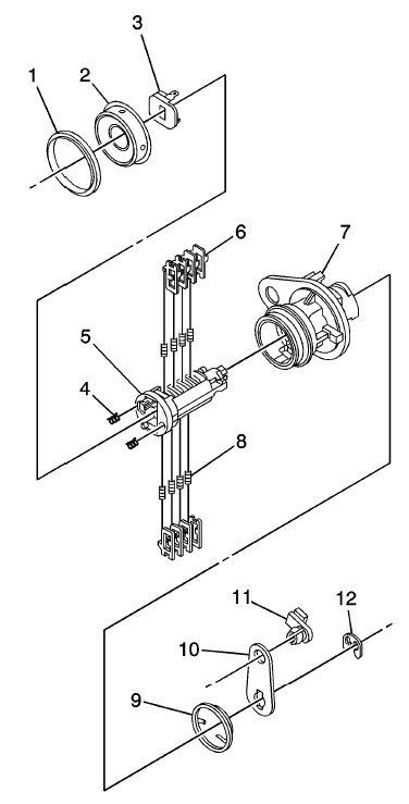
REAR COMPARTMENT LID LOCK CYLINDER CODING
The door lock cylinder uses 8 of the 8 cut positions, 1 - 8. The tumbler positions are staggered from side to side, 4 on one side and 4 on the other, are not self-retaining, and are not snap in.
1.
NOTE: All lock cylinders for side milled keys have right and left tumblers.
The location of the tooth of the tumbler determines whether it is right of left. Illustrations in this procedure show the right tumblers on the top and the left tumblers on the bottom. All tumblers are marked 1R, 1L, 2R, or 2L. The number being cut depth and the letter meaning right or left.
Hold the cylinder (5) so the side with the 4 tumbler spring pockets nearest the cylinder head faces up. This side uses left tumblers.
2. Insert the tumbler springs (8) into the 4 spring pockets.
3. Install the tumbler (6) for key cut position one in the slot nearest to the front of the lock cylinder.
Install the remaining tumblers, key cut positions 3, 5, and 7, following the key code and same process. Press the tumblers in place until they are secure.
4. Check the correct loading of the tumblers by inserting the key into the cylinder. All tumblers should be flush with the lock cylinder body.
5. Turn the cylinder so the opposite side spring pockets faces up. This side uses the right tumbler.
6. Insert the tumbler springs into the 4 spring pockets.
7. The first tumbler closest to the front of the lock cylinder to be loaded will be the second key cut position, the second number in the key code. Install the remaining tumblers for the key cut positions 4, 6, and 8. Press the tumblers in place until they are secure.
8. Check the correct loading of the tumblers by inserting the key into the cylinder. All tumblers should be flush with the lock cylinder body.
9. Insert the key and lightly lubricate the cylinder body diameter and tumbler surfaces and a small amount in the head of the cylinder using the supplied grease.
10. Install 2 springs (4) into the 2 spring pockets in the head of the lock cylinder.
11. Holding the tumblers snap the shutter assembly (3) onto the cylinder.
12. Insert the cylinder into the case assembly (7) and install the cap (2) and the gasket double (1) around the cap.
13. Add the torsion spring (9).
14. Insert the rod clip (11) in the lever (10) and place it in the cylinder assembly.
15. Insert the E-clip (12) to securely hold the lever to the cylinder.
16. Insert the key into the lock and rotate it to check for proper assembly and smooth operation.
LIFTING AND JACKING THE VEHICLE
NOTE: The use of a LOW PROFILE LIFT ARMS SYSTEM may be required to avoid unwanted contact with the vehicle's body and structure depending on lifting equipment used. Refer to the manufacture's recommendation for their applications of low profile lift arms system for their lifting equipment.
WARNING: To avoid any vehicle damage, serious personal injury or death:
- When major components are removed from the vehicle and the vehicle is supported by a hoist, support the vehicle with jack stands at the opposite end from which the components are being removed and strap the vehicle to the hoist.
- When performing work in the engine compartment or under the vehicle, ensure that the hood is fully open, or opened to its secondary latch. When the hood is opened to the secondary latch, the vehicle will disable the remote start features from the key fob and OnStar mobile app. Failure to open the hood, or open the hood to the secondary latch while doing a repair in the engine compartment or under the vehicle can result in inadvertent vehicle starting which could result in personal injury or damage to a vehicle.
WARNING: To avoid any vehicle damage, serious personal injury or death, always use the jackstands to support the vehicle when lifting the vehicle with a jack.
CAUTION: Perform the following steps before beginning any vehicle lifting or jacking procedure:
- Remove or secure all of the vehicle contents in order to avoid any shifting or any movement that may occur during the vehicle lifting or jacking procedure.
- The lifting equipment or the jacking equipment weight rating must meet or exceed the weight of the vehicle and any vehicle contents.
- The lifting equipment or the jacking equipment must meet the operational standards of the lifting equipment or jacking equipment manufacturer.
- Perform the vehicle lifting or jacking procedure on a clean, hard, dry, level surface.
- Perform the vehicle lifting or jacking procedure only at the identified lift points. DO NOT allow the lifting equipment or jacking equipment to contact any other vehicle components.
Failure to perform the previous steps could result in damage to the lifting equipment or the jacking equipment, the vehicle, and/or the vehicle contents.
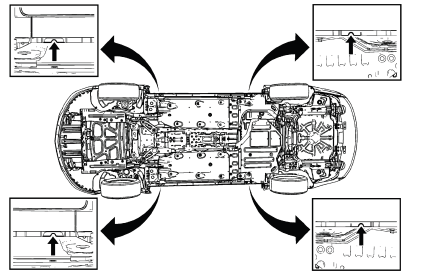
Vehicle Lifting - Frame Contact Lift
Front Lift Pads
When lifting the vehicle with a frame-contact lift, place the front lift pads on the rocker outer panel weld flange, as shown
Rear Lift Pads
When lifting the vehicle with a frame-contact lift, place the rear lift pads on the rocker outer panel weld flange, as shown.
Vehicle Jacking
CAUTION: When you are jacking the vehicle at the front locations, be certain that the jack or the jack lift pad does not contact the front fascia, front fascia air dam, or the front fenders. If such contact occurs, vehicle damage may result. When jacking at selected front locations additional clearance may be required for the jacking points.
NOTE: When you are lifting a vehicle with a service jack, block the wheels at the opposite end from which you are lifting. Use jack stands to provide additional support.
Front of Vehicle
When using a service jack under the front of the vehicle use one of the following locations: Place the service jack pad in the same location as shown for the front lift pads.
Rear of Vehicle
NOTE: Place jackstands ONLY under strong and stable vehicle structures.
Place the service jack pad in the same location as shown for the rear lift pads.
READ NEXT:
 Repair Instructions
VOLATILE MEMORY PROGRAMMING
Electric Window Lifters
Move all the windows to the topmost position and hold the switch pressed down
for 2 seconds.
Sliding Sunroof
Move the sliding roof to the respectiv
Definition of Danger, Warning, Caution, and Note
The diagnosis and repair procedures in a GM Service Manual contain both
general and specific Dangers,
Warnings, Cautions, Notes or Importants. GM is dedicated to the presentation of
service informat
SEE MORE:
Maintenance and Lubrication
SPECIFICATIONS
APPROXIMATE FLUID CAPACITIES
FLUID AND LUBRICANT RECOMMENDATIONS
MAINTENANCE ITEMS
MAINTENANCE REPLACEMENT PARTS
Replacement parts identified below by name, part number, or specification can
be obtained from your
dealer.
MAINTENANCE
MAINTENANCE SCHEDULE
The Maintenance Schedule
Front Suspension
Specifications
FASTENER SPECIFICATIONS
Single Use Threaded Fastener/Component Tightening Specifications
NOTE:
All fasteners/components listed in this table MUST BE DISCARDED and replaced
with NEW
after removal.
Reusable Threaded Fastener Tightening Specifications
NOTE:
All fasteners listed in this
