Buick Regal: DTC P0711-P0713
Diagnostic Instructions
- Perform the Diagnostic System Check prior to using this diagnostic procedure: Refer to Diagnostic System Check - Vehicle
- Review the description of Strategy Based Diagnosis: Strategy Based Diagnosis
- An overview of each diagnostic category can be found here: Refer to Diagnostic Procedure Instructions
DTC Descriptor
DTC P0711
Transmission Fluid Temperature Sensor Performance
DTC P0712
Transmission Fluid Temperature Sensor Circuit Low Voltage
DTC P0713
Transmission Fluid Temperature Sensor Circuit High Voltage
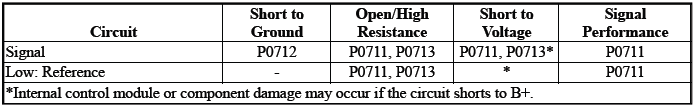
Diagnostic Fault Information
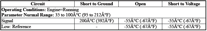
Typical Scan Tool Data
Transmission Fluid Temperature
Circuit/System Description
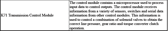
For an overview of the component/system, refer to Transmission General Description
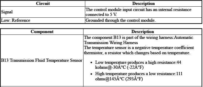
The sensor is an input to the control module K71. The input signal is used to determine the temperature of the fluid: Transmission
The control module uses this data, along with other data, to adjust or control the following:
- Driver Alert Indicator - Transmission Hot - Idle Engine
- Line Pressure
- Torque Converter Clutch
- Transmission Adaptive Values Learn
- Transmission Hot Mode
- Transmission Shifting
Conditions for Running the DTC
P0711
- DTC P0705, P0707, P0708, P0712, P0713 = Not set
- Engine Speed= Greater than 400 RPM
- Ignition Voltage=9 to 32 V
- Fail-Safe Mode=Inactive
- K71 Transmission Control Module= Communication Enabled
- Service Mode=Disabled
Frequency the DTC runs=Continuously - After the running conditions are met - For greater than 2 s
P0712
Ignition Voltage=9 to 32 V
Frequency the DTC runs=Continuously - After the running conditions are met - For greater than 2 s
P0713
- DTC P0705, P0707, P0708 = Not set
- Engine Speed= Greater than 400 RPM
- Ignition Voltage=9 to 32 V
- Transmission Range= Drive
Frequency the DTC runs=Continuously - After the running conditions are met - For greater than 2 s
Conditions for Setting the DTC
P0711Condition 1
Transmission Fluid Temperature & Engine Coolant Temperature=Not within 43ºC (77ºF) of each other
Condition 2
Transmission Fluid Temperature=The temperature does not change within 10 min & The vehicle speed has reached 40 km/h (29 MPH) at least once during this drive cycle.
Condition 3
Transmission Fluid Temperature=The temperature does not change within a predetermined time.
P0712
Transmission Fluid Temperature=Warmer than 200ºC (392ºF) - For greater than 60 s
P0713
Transmission Fluid Temperature=Colder than -55ºC (-67ºF) - For greater than 12 s
Actions Taken When the DTC Sets
DTCs listed in the DTC Descriptor Category=Type B DTC
- Autostart/Autostop=Disabled - If equipped
- Torque Converter Clutch=Disabled
- Transmission Adaptive Values Learn=Disabled
Conditions for Clearing the DTC
DTCs listed in the DTC Descriptor Category=Type B DTC
Reference Information
Schematic: Reference
Refer to Automatic Transmission Controls Wiring Schematics
Connector End View: Reference
Refer to Component Connector End View Index
Component View: Reference
Refer to Disassembled Views
Electrical Information: Reference
- Refer to Circuit Testing
- Refer to Connector Repairs
- Refer to Testing for Intermittent Conditions and Poor Connections
- Refer to Wiring Repairs
DTC Type: Reference
Refer to Powertrain Diagnostic Trouble Code (DTC) Type Definitions
Scan Tool: Reference
Refer to Control Module: References
Circuit/System Verification
1. Verify the condition does not exist: Incorrect fluid level or condition - Transmission - Refer to Transmission Fluid Level and Condition Check
- If a condition exists
Refer to Fluid Leak Diagnosis
- Go to next step: If no condition exists
2. Verify the scan tool parameter: Transmission Fluid Temperature=-39 to 199ºC (-39 to 390ºF)
- If not between -39 and 199ºC (-39 and 390ºF)
Refer to Circuit/System Testing
- Go to next step: If between -39 and 199ºC (-39 and 390ºF)
3. Operate the cold vehicle above 64 km/h (40 MPH) for 10 min.
Verify the scan tool parameter: Transmission Fluid Temperature=Temperature increases greater than 2ºC (4ºF)
- If the temperature does not increase 2ºC (4ºF) or greater
Refer to Circuit/System Testing
- Go to next step: If the temperature increases greater than 2ºC (4ºF)
4. Operate the vehicle within the Conditions for Running the DTC. You may also operate the vehicle within the conditions that you observed from the Freeze Frame/Failure Records data.
Verify the DTC does not set.
- If the DTC sets
Refer to Circuit/System Testing
- Go to next step: If the DTC is not set
5. All OK.
Circuit/System Testing
NOTE: It may take up to 2 min for all vehicle systems to power down before an accurate ground or low reference circuit continuity test can be performed.
1. Ignition/Vehicle & All vehicle systems - Off
NOTE: Twisting or tilting of the transmission control module electrical connector while disconnecting may result in bent or misaligned electrical terminal pins.
2. Remove the component: K71 Transmission Control Module.
3. Test for infinite resistance between the test points: Low: Reference circuit terminal 19 & Transmission Case.
- If less than infinite resistance
Replace the component: Automatic Transmission Wiring Harness
- Go to next step: If infinite resistance
4. Test for infinite resistance between the test points: Signal circuit terminal 10 & Transmission Case
- If less than infinite resistance
Replace the component: Automatic Transmission Wiring Harness
- Go to next step: If infinite resistance
5. Test the resistance between the test points: Low: Reference circuit terminal 19 & Signal circuit terminal 10
Verify the value is within the range listed in the table: Refer to Temperature Versus Resistance (B13 Transmission Fluid Temperature Sensor) Refer to Temperature Versus Resistance (Q27 Pressure Control Solenoid Valve) Refer to Temperature Versus Resistance (Q32 Shift Solenoid Valve 1)
- If in the specified range
Replace the component: K71 Transmission Control Module
- Go to next step: If not in the specified range
6. Test or replace the component: Automatic Transmission Wiring Harness
Repair Instructions
Perform the Diagnostic Repair Verification after completing the repair: Refer to Diagnostic Repair Verification
- Refer to Wiring Harness Wire Replacement - Automatic Transmission Wiring Harness
- For control module replacement, programming, and setup: Refer to Control Module: References
READ NEXT:
 DTC P0717, P07BF, or P07C0
Diagnostic Instructions
Perform the Diagnostic System Check prior to using this diagnostic
procedure: Refer to Diagnostic System
Check - Vehicle
Review the description of Strategy Based Diagnosi
DTC P0722, P077C, or P077D
Diagnostic Instructions
Perform the Diagnostic System Check prior to using this diagnostic
procedure: Refer to Diagnostic System
Check - Vehicle
Review the description of Strategy Based Diagnosi
DTC P0729-P0735, P076F, or P07D9
Diagnostic Instructions
Perform the Diagnostic System Check prior to using this diagnostic
procedure: Refer to Diagnostic System
Check - Vehicle
Review the description of Strategy Based Diagnosi
SEE MORE:
Draining Fluids and Oil Filter Removal
1.
Remove the oil filter (1). Remove the oil pan drain plug and allow the oil to
drain out.
2. Clean the oil filter housing in the engine block.
CAUTION: Refer to Fastener Caution.
3. Install the oil pan drain plug and tighten to 25 N.m (18 lb ft).
4. If cleaning or repairing the engine block, i
Tire Pressure Monitor
Operation
This vehicle may have a Tire
Pressure Monitor System (TPMS).
The TPMS is designed to warn the
driver when a low tire pressure
condition exists. TPMS sensors are
mounted onto each tire and wheel
assembly, excluding the spare tire
and wheel assembly. The TPMS
sensors monitor the air pressure in
the t
