Buick Regal: DTC P0815, P0816, or P0826
Diagnostic Instructions
- Perform the Diagnostic System Check prior to using this diagnostic procedure: Refer to Diagnostic System Check - Vehicle
- Review the description of Strategy Based Diagnosis: Refer to Strategy Based Diagnosis
- An overview of each diagnostic category can be found here: Refer to Diagnostic Procedure Instructions
DTC Descriptor
DTC P0815
Upshift Switch Circuit
DTC P0816
Downshift Switch Circuit
DTC P0826
Up and Down Shift Switch Circuit
Diagnostic Fault Information
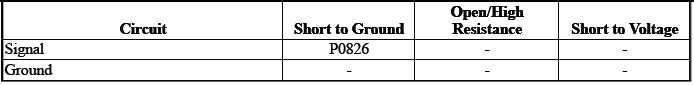
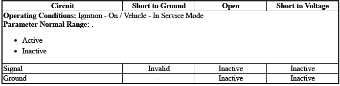
Typical Scan Tool Data
Driver Shift Request
Circuit/System Description
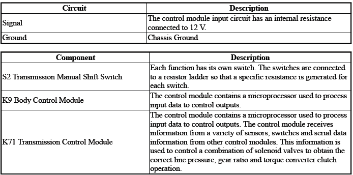
The switch S2 has an internal resistor ladder network. A specific resistance is generated dependent on the position of the switch.
Conditions for Running the DTC
- Ignition Voltage=9 to 32 V
- K71 Transmission Control Module= Communication Enabled
- K9 Body Control Module= Communication Enabled
Frequency the DTC runs=Continuously - After the running conditions are met - For 2 s
Conditions for Setting the DTC
P0815Condition 1
- Transmission Range=Park/Neutral/Reverse
- Driver Shift Request=Upshift
The above conditions must occur for greater than 2 s.
Condition 2
- Transmission Range=Drive
- Driver Shift Request=Upshift
The above conditions must occur for greater than 29 s.
P0816Condition 1
- Transmission Range=Park/Neutral/Reverse
- Driver Shift Request=Downshift
The above conditions must occur for greater than 2 s.
Condition 2
- Transmission Range=Drive
- Driver Shift Request=Downshift
The above conditions must occur for greater than 29 s.
P0826
Driver Shift Request=Illegal Mode
Actions Taken When the DTC Sets
DTCs P0815, P0816, P0826 are Type C DTCs.
Manual Shift Control=Disabled
Conditions for Clearing the DTC
DTCs P0815, P0816, P0826 are Type C DTCs.
Reference Information
Schematic: Reference
Refer to Automatic Transmission Controls Wiring Schematics.
Connector End View: Reference
Refer to Component Connector End View Index.
Component View: Reference
Refer to Disassembled Views.
Description and Operation
Refer to Transmission General Description.
Electrical Information: Reference
- Refer to Circuit Testing
- Refer to Connector Repairs
- Refer to Testing for Intermittent Conditions and Poor Connections
- Refer to Wiring Repairs
DTC Type: Reference
Refer to Powertrain Diagnostic Trouble Code (DTC) Type Definitions.
Scan Tool: Reference
Refer to Control Module: References.
Circuit/System Verification
NOTE: It may take up to 2 min for all vehicle systems to power down before an accurate ground or low reference circuit continuity test can be performed.
1. Ignition - On / Vehicle - In Service Mode
2. Verify the scan tool parameter:Driver Shift Request=Inactive
- If not the specified state
Refer to Circuit/System Testing
- Go to next step: If the specified state
3. Operate the component:S2 Transmission Manual Shift Switch
Verify the scan tool parameter:Driver Shift Request=Upshift/Downshift
- If not the specified state
Refer to Circuit/System Testing
- Go to next step: If the specified state
4. Operate the vehicle within the Conditions for Running the DTC. You may also operate the vehicle within the conditions that you observed from the Freeze Frame/Failure Records data.
Verify the DTC does not set.
- If the DTC sets
Refer to Circuit/System Testing
- Go to next step: If the DTC is not set
5. All OK.
Circuit/System Testing
NOTE: It may take up to 2 min for all vehicle systems to power down before an accurate ground or low reference circuit continuity test can be performed.
1. Ignition/Vehicle & All vehicle systems - Off.
2. Disconnect the electrical connector:S3 Transmission Shift Lever.
3. Test for less than 10 ohms between the test points:Ground circuit terminal 2@S3 Transmission Shift Lever (harness side) & Ground.
- If 10 ohms or greater
- Disconnect the ground connection:G305
- Test for less than 2 ohms between the test points:Ground circuit
terminal 2@S3 Transmission Shift
Lever (harness side) & G305
- If 2 ohms or greater - Repair the open/high resistance in the circuit.
- If less than 2 ohms - Repair the open/high resistance in the ground connection.
- Go to next step: If less than 10 ohms
4. Ignition - On / Vehicle - In Service Mode.
5. Test for greater than 10 V between the test points:Signal circuit terminal 3@S3 Transmission Shift Lever & Ground.
- If 10 V or less
- Ignition/Vehicle - Off
- Disconnect the electrical connector:K9 Body Control Module
- Test for infinite resistance between the test points:Signal circuit
terminal 3@S3 Transmission Shift
Lever (harness side) & Ground
- If less than infinite resistance - Repair the short to ground on the circuit.
- Go to next step: If infinite resistance
- Test for less than 2 ohms between the test points:Signal circuit
terminal 3@S3 Transmission Shift Lever
(harness side) & The other end of the circuit@K9 Body Control Module
(harness side)
- If 2 ohms or greater - Repair the open/high resistance in the circuit.
- If less than 2 ohms - Replace the component:K9 Body Control Module
- If greater than 10 V
6. Test or replace the component:S2 Transmission Manual Shift Switch.
Component Testing
1. Ignition/Vehicle - Off.
2. Disconnect the electrical connector:S3 Transmission Shift Lever.
3. Test the resistance between the test points:Signal terminal 3 & Ground terminal 2.
Operate the component:S2 Transmission Manual Shift Switch
- Switch - Not Pressed=5300 to 5800 ohms
- Switch - Pressed - Upshift=600 to 660 ohms
- Switch - Pressed - Downshift=1900 to 2100 ohms
- If not the specified values
Replace the component:S3 Transmission Shift Lever
- Go to next step: If the specified values
4. All OK.
Repair Instructions
Perform the Diagnostic Repair Verification after completing the repair: Refer to Diagnostic Repair Verification
- Refer to Transmission Control Lever Knob Replacement - S3 Transmission Shift Lever
- For control module replacement, programming, and setup: Refer to Control Module: References
DTC P086F
Diagnostic Instructions
- Perform the Diagnostic System Check prior to using this diagnostic procedure: Refer to Diagnostic System Check - Vehicle
- Review the description of Strategy Based Diagnosis:Strategy Based Diagnosis
- An overview of each diagnostic category can be found here: Refer to Diagnostic Procedure Instructions
DTC Descriptor
DTC P086F
Neutral Position Not Learned
Circuit/System Description
If the learned position is not stored in the control module K71, DTC P086F sets.
Conditions for Running the DTC
- DTC P0603 = Not set
- Ignition=On
DTC runs continuously when the above conditions are met.
Conditions for Setting the DTC
Neutral Position=Not Learned
Actions Taken When the DTC Sets
- DTC P086F is a Type C DTC.
- Engine Cranking=Disabled
Conditions for Clearing the DTC
DTC P086F is a Type C DTC.
Reference Information
DTC Type: Reference
Refer to Powertrain Diagnostic Trouble Code (DTC) Type Definitions.
Scan Tool: Reference
Refer to Control Module: References.
Circuit/System Verification
1. Ignition - On / Vehicle - In Service Mode.
2. Perform the scan tool learn/reset function: Refer to Gear Selector -N- Position Learn.
3. Verify the DTC does not set.
- If the DTC sets
Replace the component:K71 Transmission Control Module
- Go to next step: If the DTC does not set
4. All OK.
Repair Instructions
Perform the Diagnostic Repair Verification after completing the repair: Refer to Diagnostic Repair Verification
For control module replacement, programming, and setup: Refer to Control Module: References
READ NEXT:
 DTC P0973 or P0974
Diagnostic Instructions
Perform the Diagnostic System Check prior to using this diagnostic
procedure: Refer to Diagnostic System
Check - Vehicle
Review the description of Strategy Based Diagnosi
DTC P0976 or P0977
Diagnostic Instructions
Perform the Diagnostic System Check prior to using this diagnostic
procedure: Refer to Diagnostic System
Check - Vehicle
Review the description of Strategy Based Diagnosi
DTC P170A-P170E
Diagnostic Instructions
Perform the Diagnostic System Check prior to using this diagnostic
procedure: Refer to Diagnostic System
Check - Vehicle
Review the description of Strategy Based Diagnosi
SEE MORE:
Rear Axle Vent Replacement
Preliminary Procedure
1. Raise and support the vehicle.
2. Remove the Differential Carrier Assembly.
Rear Axle Vent
NOTE:
Use an appropriate tool to remove and install.
REAR AXLE HOUSING VENT REPLACEMENT
Preliminary Procedure
1. Raise and support the vehicle.
2. Remove the Differential Ca
DTC B2625
Diagnostic Instructions
Perform the Diagnostic System Check - Vehicle prior to using this
diagnostic procedure.
Review Strategy Based Diagnosis for an overview of the diagnostic
approach.
Diagnostic Procedure Instructions provides an overview of each
diagnostic category.
DTC Descriptor
DT
