Buick Regal: DTC P0973 or P0974
Diagnostic Instructions
- Perform the Diagnostic System Check prior to using this diagnostic procedure: Refer to Diagnostic System Check - Vehicle
- Review the description of Strategy Based Diagnosis: refer to Strategy Based Diagnosis
- An overview of each diagnostic category can be found here: refer to Diagnostic Procedure Instructions
DTC Descriptor
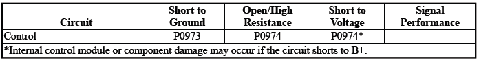
DTC P0973
Shift Solenoid Valve 1 Control Circuit Low Voltage
DTC P0974
Shift Solenoid Valve 1 Control Circuit High Voltage
Diagnostic Fault Information
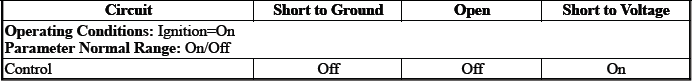
Typical Scan Tool Data
Shift Solenoid Valve 1
Shift Solenoid Valve 1 Control Circuit High Voltage Test Status
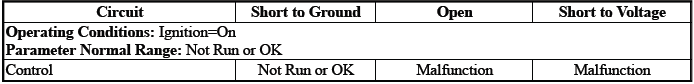
Shift Solenoid Valve 1 Control Circuit Low Voltage Test Status
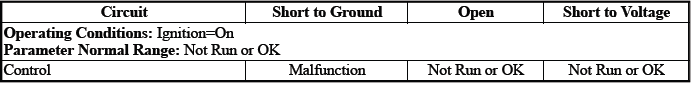
Shift Solenoid Valve 1 Control Circuit Open Test Status
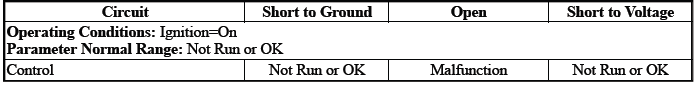
Circuit/System Description
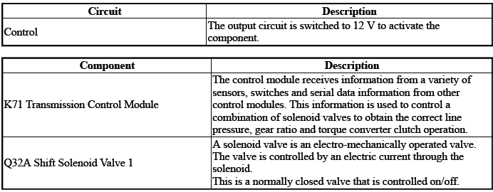
Depending on the state of the pressure control solenoids, the position of the component Q32A will cause either a gear shift or 1st gear engine braking.
Conditions for Running the DTC
Ignition Voltage=9 to 32 V
Frequency the DTC runs=Continuously - After the running conditions are met - For 2 s
Conditions for Setting the DTC
Control Circuit=Commanded state does not match the actual state
Actions Taken When the DTC Sets
DTCs listed in the DTC Descriptor Category=Type A DTC
- Fail-Safe Mode=Active
- Learning=Disabled
- Transmission gear allowed=3rd Gear - After a stop
Conditions for Clearing the DTC
DTCs listed in the DTC Descriptor Category=Type A DTC
Reference Information
Schematic: Reference
Refer to Automatic Transmission Controls Wiring Schematics.
Connector End View: Reference
Refer to Component Connector End View Index
Component View: Reference
Refer to Disassembled Views.
Description and Operation
Refer to Transmission General Description.
Electrical Information: Reference
- Refer to Circuit Testing
- Refer to Connector Repairs
- Refer to Testing for Intermittent Conditions and Poor Connections
- Refer to Wiring Repairs
DTC Type: Reference
Refer to Powertrain Diagnostic Trouble Code (DTC) Type Definitions.
Scan Tool: Reference
Refer to Control Module: References.
Circuit/System Verification
1. Engine - Running.
2. Perform the scan tool control function:Shift Transmission Gear - Upshift & Downshift.
Verify the scan tool parameter:
- Shift Solenoid Valve 1 Control Circuit High Voltage Test Status=Not Run or OK
- Shift Solenoid Valve 1 Control Circuit Low Voltage Test Status=Not Run or OK
- Shift Solenoid Valve 1 Control Circuit Open Test Status=Not Run or OK
- If not the specified state
Refer to Circuit/System Testing
- Go to next step: If the specified state
3. Perform the scan tool control function:Shift Solenoid Valve 1 - Enable & Disable
Verify the component produces a clicking sound:Q32A Shift Solenoid Valve 1
- If the component does not produce a sound
Refer to Circuit/System Testing
- Go to next step: If the component produces a sound
4. Operate the vehicle within the Conditions for Running the DTC. You may also operate the vehicle within the conditions that you observed from the Freeze Frame/Failure Records data.
Verify the DTC does not set.
- If the DTC sets
Refer to Circuit/System Testing
- Go to next step: If the DTC is not set
5. All OK.
Circuit/System Testing
1. Ignition/Vehicle - Off.
2. Remove the component:K71 Transmission Control Module.
NOTE: The component's temperature should be 19 to 21ºC (66 to 70ºF) while testing.
3. Test for 11 to 15 ohms between the test points:Control circuit terminal 23 X2 & Transmission Case
- If not between 11 and 15 ohms
- Remove the component:Control Valve Body Cover
- Disconnect the electrical connector:Q32A Shift Solenoid Valve 1
- Test for less than 2 ohms between the test points:Control circuit
terminal 1@Component harness &
Terminal 23 X2@Control module harness
- If greater than 2 ohms - Replace the component:Automatic Transmission Wiring Harness
- If less than 2 ohms - Replace the component:Control Valve Body
- Go to next step: If between 11 and 15 ohms
4. Replace the component:K71 Transmission Control Module
Component Testing
1. Ignition/Vehicle - Off.
2. Disconnect the electrical connector:Q32A Shift Solenoid Valve 1.
NOTE: The component's temperature should be 19 to 21ºC (66 to 70ºF) while testing.
3. Test for 11 to 15 ohms between the test points:Control terminal 1 & Transmission Case
- If not between 11 and 15 ohms
Replace the component:Control Valve Body
- Go to next step: If between 11 and 15 ohms
4. All OK.
Repair Instructions
Perform the Diagnostic Repair Verification after completing the repair: Refer to Diagnostic Repair Verification
- Refer to Control Valve Body Replacement
- Refer to Wiring Harness Wire Replacement
- For control module replacement, programming, and setup: Refer to Control Module: References
READ NEXT:
 DTC P0976 or P0977
Diagnostic Instructions
Perform the Diagnostic System Check prior to using this diagnostic
procedure: Refer to Diagnostic System
Check - Vehicle
Review the description of Strategy Based Diagnosi
DTC P170A-P170E
Diagnostic Instructions
Perform the Diagnostic System Check prior to using this diagnostic
procedure: Refer to Diagnostic System
Check - Vehicle
Review the description of Strategy Based Diagnosi
DTC P175F
Diagnostic Instructions
Perform the Diagnostic System Check prior to using this diagnostic
procedure: Refer to Diagnostic System
Check - Vehicle
Review the description of Strategy Based Diagnosi
SEE MORE:
Upper Intermediate Steering Shaft Replacement
Removal Procedure
1.
Upper Intermediate Steering Shaft Upper Bolt(1) - Remove.
2. Upper Intermediate Steering Shaft(2)@Steering Column - Separate.
3.
Release the upper intermediate steering shaft boot (1) from the retaining
tabs (2) on the intermediate
steering shaft inner boot.
4.
Slide the u
DTC B3976
Diagnostic Instructions
Perform the Diagnostic System Check - Vehicle prior to using this
diagnostic procedure.
Review Strategy Based Diagnosis for an overview of the diagnostic
approach.
Diagnostic Procedure Instructions provides an overview of each
diagnostic category.
DTC Descriptor
DT
