Buick Regal: DTC P175F
Diagnostic Instructions
- Perform the Diagnostic System Check prior to using this diagnostic procedure: Refer to Diagnostic System Check - Vehicle
- Review the description of Strategy Based Diagnosis:Strategy Based Diagnosis
- An overview of each diagnostic category can be found here: Refer to Diagnostic Procedure Instructions
DTC Descriptor
DTC P175F
Acceleration Sensor Signal Message Counter Incorrect
Circuit/System Description
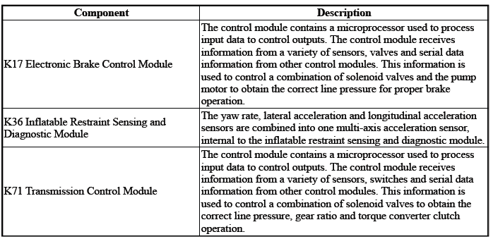
Inflatable Restraint Sensing and Diagnostic Module communicates with the electronic brake control module and transmission control module via serial data. The electronic brake control module activates the stability control function depending on the multi-axis acceleration sensor input. The inflatable restraint sensing and diagnostic module uses the multi-axis acceleration sensor to determine if the vehicle is in a roll over or near collision incident.
The transmission control module uses the rate of vehicle acceleration to improve vehicle performance and transmission shift feel. The transmission control module sets this DTC when it detects a discrepancy in the structure of the message, causing the signal message integrity to be questioned.
Conditions for Running the DTC
- DTC U0121 = Not set
- Ignition=On - For greater than 3 s
- Serial Data=Enabled
Frequency the DTC runs=Continuously - After the running conditions are met
Conditions for Setting the DTC
Serial Data=Message Counter Incorrect - Between the following control modules:
- K71 Transmission Control Module
- K17 Electronic Brake Control Module
The above condition (s) must occur 5 times.
Actions Taken When the DTC Sets
DTCs listed in the DTC Descriptor Category=Type C DTC
Conditions for Clearing the DTC
DTCs listed in the DTC Descriptor Category=Type C DTC
Reference Information
DTC Type: Reference
Refer to Powertrain Diagnostic Trouble Code (DTC) Type Definitions.
Scan Tool: Reference
Refer to Control Module: References.
Circuit/System Verification
1. Verify there are no DTCs set related to the following system/component:Serial Data
- If other DTCs are set
Refer to: Diagnostic Trouble Code (DTC) List - Vehicle
- If no other DTCs are set
- Replace the component:K71 Transmission Control Module
- Operate the vehicle within the Conditions for Running the DTC.
Verify the DTC does not set.
- If the DTC sets - Replace the component:K17 Electronic Brake Control Module
- Go to next step: If the DTC is not set
- All OK.
- Go to next step: If no DTC is set
2. All OK.
Repair Instructions
Perform the Diagnostic Repair Verification after completing the repair: Refer to Diagnostic Repair Verification
For control module replacement, programming, and setup: Refer to Control Module: References
DTC P1761
Diagnostic Instructions
- Perform the Diagnostic System Check prior to using this diagnostic procedure: Refer to Diagnostic System Check - Vehicle
- Review the description of Strategy Based Diagnosis:Strategy Based Diagnosis
- An overview of each diagnostic category can be found here: Refer to Diagnostic Procedure Instructions
DTC Descriptor
DTC P1761
Up and Down Shift Switch Signal Message Counter Incorrect
Circuit/System Description
Control modules connected to the serial data circuits monitor the communication during normal vehicle operation.
Operating information and commands are exchanged among the control modules. Each module on the serial data circuit maintains a transmit error counter and a receive error counter. The counter values increase with detected errors and decrease with error-free messages.
Conditions for Running the DTC
- K9 Body Control Module= Communication Enabled
- K71 Transmission Control Module= Communication Enabled
- Ignition Voltage=9 to 32 V
Frequency the DTC runs=Continuously - After the running conditions are met
Conditions for Setting the DTC
Serial Data=Message Counter Incorrect - Between the following control modules:
- K71 Transmission Control Module
- K9 Body Control Module
The above condition (s) must occur 5 times.
Actions Taken When the DTC Sets
- DTCs listed in the DTC Descriptor Category=Type C DTC
- Manual Shift Control=Disabled
Conditions for Clearing the DTC
DTCs listed in the DTC Descriptor Category=Type C DTC
Reference Information
DTC Type: Reference
Refer to Powertrain Diagnostic Trouble Code (DTC) Type Definitions.
Scan Tool: Reference
Refer to Control Module: References.
Circuit/System Verification
1. Verify there are no DTCs set related to the following system/component:Serial Data
- If other DTCs are set
Refer to: Diagnostic Trouble Code (DTC) List - Vehicle
- If no other DTCs are set
- Replace the component:K71 Transmission Control Module
- Operate the vehicle within the Conditions for Running the DTC.
Verify the DTC does not set.
- If the DTC sets - Replace the component:K9 Body Control Module
- Go to next step: If the DTC is not set
- All OK.
- Go to next step: If no DTC is set
2. All OK.
Repair Instructions
Perform the Diagnostic Repair Verification after completing the repair: Refer to Diagnostic Repair Verification
For control module replacement, programming, and setup: Refer to Control Module: References
DTC P1775
Diagnostic Instructions
- Perform the Diagnostic System Check prior to using this diagnostic procedure: Refer to Diagnostic System Check - Vehicle
- Review the description of Strategy Based Diagnosis:Strategy Based Diagnosis
- An overview of each diagnostic category can be found here: Refer to Diagnostic Procedure Instructions
DTC Descriptor
DTC P1775
Transmission Range Request Signal Message Counter Incorrect
Circuit/System Description
For an overview of the component/system, refer to Electronic Component Description
Control modules connected to the serial data circuits monitor the communication during normal vehicle operation.
Operating information and commands are exchanged among the control modules. Each module on the serial data circuit maintains a transmit error counter and a receive error counter. The counter values increase with detected errors and decrease with error-free messages.
Conditions for Running the DTC
- Battery Voltage=9 to 32 V
- Ignition Voltage =9 to 32 V
- No other DTCs related to the concerned component are set.
Conditions for Setting the DTC
Serial Data=Message Counter Incorrect - Between the following control modules:
- K9 Body Control Module
- K71 Transmission Control Module
Actions Taken When the DTC Sets
DTCs listed in the DTC Descriptor Category=Type B DTC
Conditions for Clearing the DTC
DTCs listed in the DTC Descriptor Category=Type B DTC
Reference Information
DTC Type: Reference
Refer to Powertrain Diagnostic Trouble Code (DTC) Type Definitions.
Scan Tool: Reference
Refer to Control Module: References.
Circuit/System Verification
NOTE: DTC P1775 is an informational DTC.
1. Ignition - On / Vehicle - In Service Mode
2. Verify there are no DTCs set related to the following system/component:Serial Data
- If a related DTC is set
Refer to: Diagnostic Trouble Code (DTC) List - Vehicle
- Go to next step: If a related DTC is not set
- Ignition/Vehicle - Off
- Replace the component:K71 Transmission Control Module
- Operate the vehicle within the Conditions for Running the DTC.
- Verify the DTC does not set.
- If the DTC sets - Replace the component:K9 Body Control Module
- Go to next step: If the DTC is not set
- All OK.
- Go to next step: If no DTC is set
3. All OK.
Repair Instructions
Perform the Diagnostic Repair Verification after completing the repair: Refer to Diagnostic Repair Verification.
For control module replacement, programming, and setup: Refer to Control Module: References.
READ NEXT:
 DTC P2716, P2720, or P2721
Diagnostic Instructions
Perform the Diagnostic System Check prior to using this diagnostic
procedure: Refer to Diagnostic System
Check - Vehicle
Review the description of Strategy Based Diagnosi
DTC P2725, P2729, or P2730
Diagnostic Instructions
Perform the Diagnostic System Check prior to using this diagnostic
procedure: Refer to Diagnostic System
Check - Vehicle
Review the description of Strategy Based Diagnosi
DTC P2734, P2738, or P2739
Diagnostic Instructions
Perform the Diagnostic System Check prior to using this diagnostic
procedure: Refer to Diagnostic System
Check - Vehicle
Review the description of Strategy Based Diagnosi
SEE MORE:
OnStar Description and Operation (UE1 with IOB/IO6)
This OnStar system consists of the following components:
Telematics communication interface control module
OnStar three button assembly
Microphone
Cellular antenna
Navigation antenna
Bluetooth antenna (If equipped)
Back up battery (If equipped)
WiFi Hotspot (If equipped)
TTY (Teletyp
Towing with a Stability Control
System
When towing, the stability control
system might be heard. The system
reacts to vehicle movement caused
by the trailer, which mainly occurs
during cornering. This is normal
when towing heavier trailers.
Following Distance
Stay at least twice as far behind the
vehicle ahead as you would when
driving w
