Buick Regal: DTC P2716, P2720, or P2721
Diagnostic Instructions
- Perform the Diagnostic System Check prior to using this diagnostic procedure: Refer to Diagnostic System Check - Vehicle
- Review the description of Strategy Based Diagnosis: Refer to Strategy Based Diagnosis
- An overview of each diagnostic category can be found here: Refer to Diagnostic Procedure Instructions
DTC Descriptor
DTC P2716
Pressure Control Solenoid Valve 4 Control Circuit
DTC P2720
Pressure Control Solenoid Valve 4 Control Circuit Low Voltage
DTC P2721
Pressure Control Solenoid Valve 4 Control Circuit High Voltage
Diagnostic Fault Information
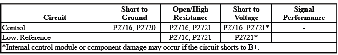
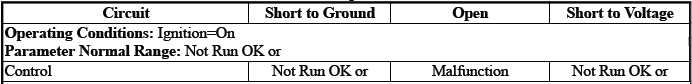
Typical Scan Tool Data
Pressure Control Solenoid Valve 4 Control Circuit High Voltage Test Status
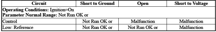
Pressure Control Solenoid Valve 4 Control Circuit Low Voltage Test Status
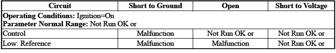
Pressure Control Solenoid Valve 4 Control Circuit Open Test Status

Circuit/System Description
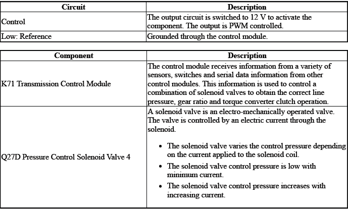
The solenoid valve controls the flow of transmission fluid to the hydraulic actuator that controls the C4 clutch.
Conditions for Running the DTC
- { P2716 }DTC P0606, P0657, P0962, P0963, P0966, P0967, P0970, P0971, P2720, P2721, P2729, P2730, P2738, P2739 = Not set
- { P2720 }DTC P0606, P0657, P0963, P0967, P0971, P2721, P2730, P2739 = Not set
- { P2721 }DTC P0606, P0657, P0962, P0966, P0970, P2720, P2729, P2738, = Not set
- Ignition Voltage=9 to 32 V
Frequency the DTC runs=Continuously - After the running conditions are met
Conditions for Setting the DTC
P2716
Control Circuit=Commanded state does not match the actual state
P2720
Control Circuit=Less than 20 mA - For greater than 1 s
P2721
Control Circuit=Greater than 1358 mA - For greater than 1 s
Actions Taken When the DTC Sets
DTCs listed in the DTC Descriptor Category=Type A DTC
- Fail-Safe Mode=Active
- Learning=Disabled
- Transmission gear allowed=3rd Gear - After a stop
Conditions for Clearing the DTC
DTCs listed in the DTC Descriptor Category=Type A DTC
Reference Information
Schematic: Reference
Refer to Automatic Transmission Controls Wiring Schematics.
Connector End View: Reference
Refer to Component Connector End View Index.
Component View: Reference
Refer to Disassembled Views.
Description and Operation
Refer to Transmission General Description.
Electrical Information: Reference
- Refer to Circuit Testing
- Refer to Connector Repairs
- Refer to Testing for Intermittent Conditions and Poor Connections
- Refer to Wiring Repairs
DTC Type: Reference
Refer to Powertrain Diagnostic Trouble Code (DTC) Type Definitions
Scan Tool: Reference
Refer to Control Module: References
Circuit/System Verification
1. Ignition - On / Vehicle - In Service Mode
2. Perform the scan tool control function:Pressure Control Solenoid Valve 4 - Increase & Decrease
Verify the scan tool parameter:
- Pressure Control Solenoid Valve 4 Control Circuit High Voltage Test Status=Not Run or OK
- Pressure Control Solenoid Valve 4 Control Circuit Low Voltage Test Status=Not Run or OK
- Pressure Control Solenoid Valve 4 Control Circuit Open Test Status=Not Run or OK
- If not the specified state
Refer to Circuit/System Testing
- Go to next step: If the specified state
3. Perform the scan tool control function:Pressure Control Solenoid Valve 4 - Increase & Decrease Verify the component produces a clicking sound:Q27D Pressure Control Solenoid Valve 4
- If the component does not produce a sound
Refer to Circuit/System Testing
- Go to next step: If the component produces a sound
4. Operate the vehicle within the Conditions for Running the DTC. You may also operate the vehicle within the conditions that you observed from the Freeze Frame/Failure Records data.
Verify the DTC does not set.
- If the DTC sets
Refer to Circuit/System Testing
- Go to next step: If the DTC is not set
5. All OK.
Circuit/System Testing
NOTE: It may take up to 2 min for all vehicle systems to power down before an accurate ground or low reference circuit continuity test can be performed.
1. Ignition/Vehicle & All vehicle systems - Off
NOTE: Twisting or tilting of the transmission control module electrical connector while disconnecting may result in bent or misaligned electrical terminal pins.
2. Remove the component:K71 Transmission Control Module
3. Test for 5.0 to 5.6 ohms between the test points:Control circuit terminal 21 & Low: Reference circuit terminal 22
- If not between 5.0 and 5.6 ohms
- Remove the component:Control Valve Body Cover
- Disconnect the electrical connector:Q27D Pressure Control Solenoid Valve 4
- Test for less than 2 ohms between the test points:
- Control circuit terminal 2@Component harness & Control circuit terminal 21@Control module harness
- Low: Reference circuit terminal 1@Component harness & Low: Reference circuit terminal 22@Control module harness
- If 2 ohms or greater - Replace the component:Automatic Transmission Wiring Harness
- If less than 2 ohms - Replace the component:Q27D Pressure Control Solenoid Valve 4
- Go to next step: If between 5.0 and 5.6 ohms
4. Test for infinite resistance between the test points:
- Control circuit terminal 21 & Transmission Case
- Low: Reference circuit terminal 22 & Transmission Case
- If less than infinite resistance
- Remove the component:Control Valve Body Cover
- Disconnect the electrical connector:Q27D Pressure Control Solenoid Valve 4
- Test for infinite resistance between the test points:
- Control circuit terminal 2@Component harness & Transmission Case
- Low: Reference circuit terminal 1@Component harness & Transmission Case
- If less than infinite resistance - Replace the component:Automatic Transmission Wiring Harness
- If infinite resistance - Replace the component:Control Valve Body
- Go to next step: If infinite resistance
5. Replace the component:K71 Transmission Control Module
Component Testing
1. Ignition/Vehicle - Off
2. Disconnect the electrical connector:Q27D Pressure Control Solenoid Valve 4
NOTE: The component's temperature should be 19 to 21ºC (66 to 70ºF) while testing.
3. Test for 5.0 to 5.6 ohms between the test points:Control terminal 2 & Low: Reference terminal 1
- If not between 5.0 and 5.6 ohms
Replace the component:Control Valve Body
- Go to next step: If between 5.0 and 5.6 ohms
4. Test for infinite resistance between the test points:Each terminal of the component & The component's housing
- If less than infinite resistance
Replace the component:Control Valve Body
- Go to next step: If infinite resistance
5. All OK.
Repair Instructions
Perform the Diagnostic Repair Verification after completing the repair: Refer to Diagnostic Repair Verification
- Refer to Control Valve Body Replacement
- Refer to Wiring Harness Wire Replacement
- For control module replacement, programming, and setup: Refer to Control Module: References
READ NEXT:
 DTC P2725, P2729, or P2730
Diagnostic Instructions
Perform the Diagnostic System Check prior to using this diagnostic
procedure: Refer to Diagnostic System
Check - Vehicle
Review the description of Strategy Based Diagnosi
DTC P2734, P2738, or P2739
Diagnostic Instructions
Perform the Diagnostic System Check prior to using this diagnostic
procedure: Refer to Diagnostic System
Check - Vehicle
Review the description of Strategy Based Diagnosi
DTC P2761, P2763, or P2764
Diagnostic Instructions
Perform the Diagnostic System Check prior to using this diagnostic
procedure: Refer to Diagnostic System
Check - Vehicle
Review the description of Strategy Based Diagnosi
SEE MORE:
DTC B2530
Diagnostic Instructions
Perform the Diagnostic System Check - Vehicle prior to using this
diagnostic procedure.
Review Strategy Based Diagnosis for an overview of the diagnostic
approach.
Diagnostic Procedure Instructions provides an overview of each
diagnostic category.
DTC Descriptor
DT
Engine Coolant Fan Wiring Harness Replacement (3.6L LGX)
Removal Procedure
1. Front Bumper Fascia - Remove.
2. Headlamp- Left Side - Remove.
3.
Engine Coolant Fan Wiring Harness (1) @ Air Conditioning Refrigerant Pressure
Sensor -
Disconnect.
4. Engine Coolant Fan Wiring Harness (2) @ Air Conditioning Evaporator Tube -
Unclip.
5.
Engine Coolant Fan
