Buick Regal: DTC P2761, P2763, or P2764
Diagnostic Instructions
- Perform the Diagnostic System Check prior to using this diagnostic procedure: Refer to Diagnostic System Check - Vehicle
- Review the description of Strategy Based Diagnosis: Refer to Strategy Based Diagnosis
- An overview of each diagnostic category can be found here: Refer to Diagnostic Procedure Instructions
DTC Descriptor
DTC P2761
Torque Converter Clutch (TCC) Pressure Control Solenoid Valve Control Circuit
DTC P2763
Torque Converter Clutch (TCC) Pressure Control Solenoid Valve Control Circuit High Voltage
DTC P2764
Torque Converter Clutch (TCC) Pressure Control Solenoid Valve Control Circuit Low Voltage
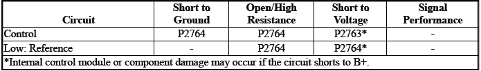
Diagnostic Fault Information
Typical Scan Tool Data
TCC Pressure Control Solenoid Valve Control Circuit High Voltage Test Status
TCC Pressure Control Solenoid Valve Control Circuit Low Voltage Test Status
TCC Pressure Control Solenoid Valve Control Circuit Open Test Status
Circuit/System Description
For an overview of the component/system, refer to Transmission General Description
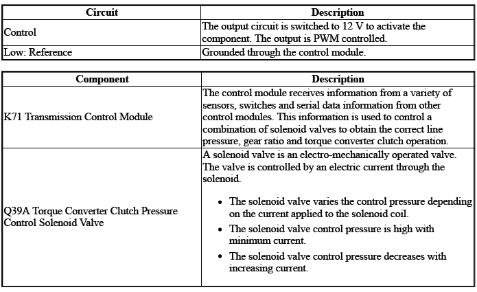
The solenoid valve controls the flow of transmission fluid to the hydraulic actuator that controls the torque converter clutch engagement.
Conditions for Running the DTC
- { P2761 }DTC P2763, P2764 = Not set
- { P2763 }DTC P2764 = Not set
- { P2764 }DTC P2763 = Not set
- Engine Speed= Greater than 400 RPM for greater than 2 s
- Fail-Safe Mode=Inactive
- Ignition Voltage=9 to 32 V
- K71 Transmission Control Module= Communication Enabled
- Transmission Range= Drive
Frequency the DTC runs=Continuously - After the running conditions are met
Conditions for Setting the DTC
P2761
Control Circuit=Commanded state does not match the actual state
P2763
Control Circuit=Less than 20 mA - For 1 s
P2764
Control Circuit=Greater than 1358 mA - For 1 s
Actions Taken When the DTC Sets
DTCs listed in the DTC Descriptor Category=Type B DTC
- { P2763 }Autostart/Autostop=Disabled - If equipped
- Learning=Disabled
- Transmission gear allowed=Gear 2 & Reverse - After a stop
Conditions for Clearing the DTC
DTCs listed in the DTC Descriptor Category=Type B DTC
Reference Information
Schematic: Reference
Refer to Automatic Transmission Controls Wiring Schematics
Connector End View: Reference
Refer to Component Connector End View Index
Component View: Reference
Refer to Disassembled Views
Electrical Information: Reference
- Refer to Circuit Testing
- Refer to Connector Repairs
- Refer to Testing for Intermittent Conditions and Poor Connections
- Refer to Wiring Repairs
DTC Type: Reference
Refer to Powertrain Diagnostic Trouble Code (DTC) Type Definitions
Scan Tool: Reference
Refer to Control Module: References
Circuit/System Verification
1. Ignition - On / Vehicle - In Service Mode
2. Perform the scan tool control function:TCC Solenoid Valve - On & Off
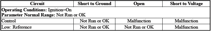
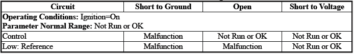
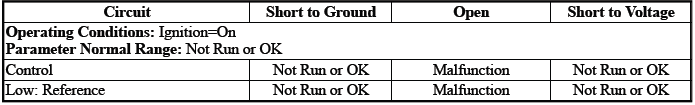
Verify the scan tool parameter:
- TCC Pressure Control Solenoid Valve Control Circuit High Voltage Test Status=Not Run or OK
- TCC Pressure Control Solenoid Valve Control Circuit Low Voltage Test Status=Not Run or OK
- TCC Pressure Control Solenoid Valve Control Circuit Open Test Status=Not Run or OK
- If not the specified state
Refer to Circuit/System Testing
- Go to next step: If the specified state
3. Perform the scan tool control function:TCC Solenoid Valve - Enable & Disable
Verify the component produces a clicking sound:Q39A Torque Converter Clutch Pressure Control Solenoid Valve
- If the component does not produce a sound
Refer to Circuit/System Testing
- Go to next step: If the component produces a sound
4. Operate the vehicle within the Conditions for Running the DTC. You may also operate the vehicle within the conditions that you observed from the Freeze Frame/Failure Records data.
Verify the DTC does not set.
- If the DTC sets
Refer to Circuit/System Testing
- Go to next step: If the DTC is not set
5. All OK.
Circuit/System Testing
NOTE: It may take up to 2 min for all vehicle systems to power down before an accurate ground or low reference circuit continuity test can be performed.
1. Ignition/Vehicle & All vehicle systems - Off
NOTE: Twisting or tilting of the transmission control module electrical connector while disconnecting may result in bent or misaligned electrical terminal pins.
2. Remove the component:K71 Transmission Control Module
3. Test for 5.0 to 5.6 ohms between the test points:Control circuit terminal 2 & Low: Reference circuit terminal 1
- If not between 5.0 and 5.6 ohms
- Remove the component:Control Valve Body Cover
- Disconnect the electrical connector:Q39A Torque Converter Clutch Pressure Control Solenoid Valve
- Test for less than 2 ohms between the test points:
- Control circuit terminal 2@Component harness & Control circuit terminal 2@Control module harness
- Low: Reference circuit terminal 1@Component harness & Low: Reference circuit terminal 1@Control module harness
- If 2 ohms or greater - Replace the component:Automatic Transmission Wiring Harness
- If less than 2 ohms - Replace the component:Control Valve Body
- Go to next step: If between 5.0 and 5.6 ohms
4. Test for infinite resistance between the test points:
- Control circuit terminal 2 & Transmission Case
- Low: Reference circuit terminal 1 & Transmission Case
- If less than infinite resistance
- Remove the component:Control Valve Body Cover
- Disconnect the electrical connector:Q39A Torque Converter Clutch Pressure Control Solenoid Valve
- Test for infinite resistance between the test points:
- Control circuit terminal 2@Component harness & Transmission Case
- Low: Reference circuit terminal 1@Component harness & Transmission Case
- If less than infinite resistance - Replace the component:Automatic Transmission Wiring Harness
- If infinite resistance - Replace the component:Control Valve Body
- Go to next step: If infinite resistance
5. Replace the component:K71 Transmission Control Module
Component Testing
1. Ignition/Vehicle - Off
2. Disconnect the electrical connector:Q39A Torque Converter Clutch Pressure Control Solenoid Valve
NOTE: The component's temperature should be 19 to 21ºC (66 to 70ºF) while testing.
3. Test for 5.0 to 5.6 ohms between the test points:Control terminal 2 & Low: Reference terminal 1
- If not between 5.0 and 5.6 ohms
Replace the component:Control Valve Body
- Go to next step: If between 5.0 and 5.6 ohms
4. Test for infinite resistance between the test points:Each terminal of the component & The component's housing
- If less than infinite resistance
Replace the component:Control Valve Body
- Go to next step: If infinite resistance
5. All OK.
Repair Instructions
Perform the Diagnostic Repair Verification after completing the repair: Refer to Diagnostic Repair Verification
- Refer to Control Valve Body Replacement
- Refer to Wiring Harness Wire Replacement
- For control module replacement, programming, and setup: Refer to Control Module: References
READ NEXT:
 DTC P2808
Diagnostic Instructions
Perform the Diagnostic System Check prior to using this diagnostic
procedure: Refer to Diagnostic System
Check - Vehicle
Review the description of Strategy Based Diagnosi
DTC P2814 or P2815
Diagnostic Instructions
Perform the Diagnostic System Check prior to using this diagnostic
procedure: Refer to Diagnostic System
Check - Vehicle
Review the description of Strategy Based Diagnosi
Symptoms - Automatic Transmission
NOTE: Use the symptom tables only if the following conditions are met:
Refer to Diagnostic Starting Point - Vehicle.
There are no DTCs set.
The control modules can communicate via the serial data
SEE MORE:
Turbocharger Heat Shield Replacement
Turbocharger Heat Shield Bolt [3x]
CAUTION: Refer to Fastener Caution.
NOTE: In the event that a bolt breaks upon removal of components, perform
an extraction of the broken bolt.
Tighten 14 N.m (10 lb ft)
Turbocharger Heat Shield
TURBOCHARGER REPLACEMENT
Removal Procedure
CAUTION: If a tur
Repair Instructions
Ambient Air Temperature Calculation Reset (with Ambient Air
Temperature Sensor Wired to ECM)
Diagnostic Instructions
Perform the Diagnostic System Check prior to using this diagnostic
procedure: Diagnostic
System Check - Vehicle
Review the description of Strategy Based Diagnosis:Strategy Based
