Buick Regal: DTC P2814 or P2815
Diagnostic Instructions
- Perform the Diagnostic System Check prior to using this diagnostic procedure: Refer to Diagnostic System Check - Vehicle
- Review the description of Strategy Based Diagnosis: Refer to Strategy Based Diagnosis
- An overview of each diagnostic category can be found here: Refer to Diagnostic Procedure Instructions
DTC Descriptor
DTC P2814
Pressure Control Solenoid Valve 7 Control Circuit Low Voltage
DTC P2815
Pressure Control Solenoid Valve 7 Control Circuit High Voltage
Diagnostic Fault Information
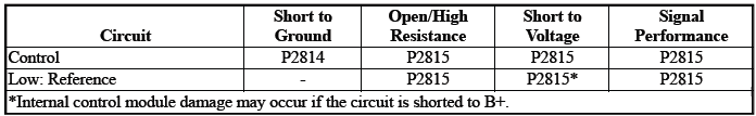
Typical Scan Tool Data
Pressure Control Solenoid Valve 7 Control Circuit Low Voltage Test Status
Pressure Control Solenoid Valve 7 Control Circuit Open Test Status
Pressure Control Solenoid Valve 7 High Voltage Test Status
Circuit/System Description
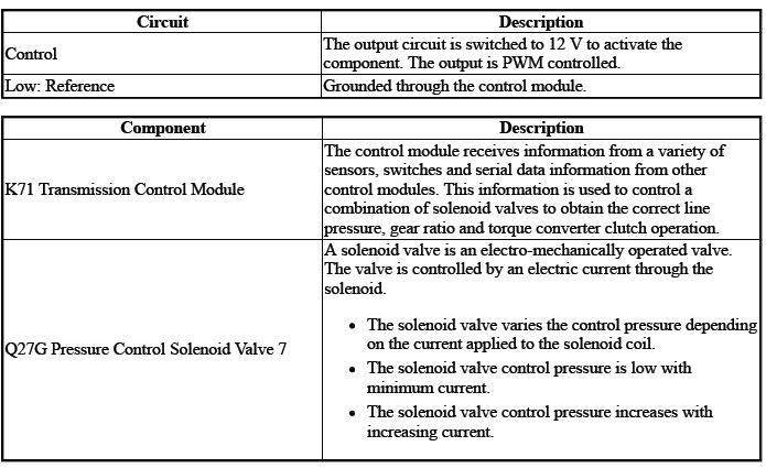
The solenoid valve controls the flow of transmission fluid to the hydraulic actuator that controls the C1 clutch. - During an autostart or autostop event
Conditions for Running the DTC
Ignition Voltage=9 to 32 V
DTCs run continuously when the above conditions are met for greater than 2 s.
Conditions for Setting the DTC
Control circuit=Commanded state does not match the actual state
Actions Taken When the DTC Sets
DTCs P2814, P2815 are Type B DTCs.
Autostart/Autostop=Disabled
Conditions for Clearing the DTC
DTCs P2814, P2815 are Type B DTCs.
Reference Information
Schematic: Reference
Refer to Automatic Transmission Controls Wiring Schematics
Connector End View: Reference
Refer to Component Connector End View Index
Component View: Reference
Refer to Disassembled Views
Description and Operation
Refer to Transmission General Description
Electrical Information: Reference
- Refer to Circuit Testing
- Refer to Connector Repairs
- Refer to Testing for Intermittent Conditions and Poor Connections
- Refer to Wiring Repairs
DTC Type: Reference
Refer to Powertrain Diagnostic Trouble Code (DTC) Type Definitions
Scan Tool: Reference
Refer to Control Module: References
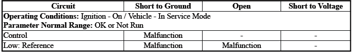
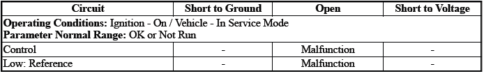
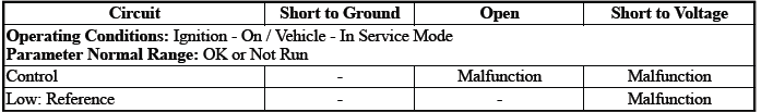
Circuit/System Verification
1. Ignition - On / Vehicle - In Service Mode
2. Perform the scan tool control function:Auxiliary Transmission Fluid Pump - Enable & Disable
Verify the scan tool parameter:
- Pressure Control Solenoid Valve 7 High Voltage Test Status= OK or Not Run
- Pressure Control Solenoid Valve 7 Control Circuit Low Voltage Test Status= OK or Not Run
- Pressure Control Solenoid Valve 7 Control Circuit Open Test Status= OK or Not Run
- If not the specified state
Refer to Circuit/System Testing
- Go to next step: If the specified state
3. Perform the scan tool control function:Auxiliary Transmission Fluid Pump - Enable & Disable
Verify the component produces a clicking sound:Q27G Pressure Control Solenoid Valve 7
- If the component does not produce a sound
Refer to Circuit/System Testing
- Go to next step: If the component produces a sound
4. Operate the vehicle within the Conditions for Running the DTC. You may also operate the vehicle within the conditions that you observed from the Freeze Frame/Failure Records data.
5. Verify the DTC does not set.
- If the DTC sets
Refer to Circuit/System Testing
- Go to next step: If the DTC is not set
6. All OK.
Circuit/System Testing
NOTE: It may take up to 2 min for all vehicle systems to power down before an accurate ground or low reference circuit continuity test can be performed.
1. Ignition/Vehicle & All vehicle systems - Off
NOTE: Twisting or tilting of the transmission control module electrical connector while disconnecting may result in bent or misaligned electrical terminal pins.
2. Remove the component:K71 Transmission Control Module
NOTE: The component's temperature should be 19 to 21ºC (66 to 70ºF) while testing.
3. Test for 5.0 to 5.6 ohms between the test points:Control circuit terminal 30 & Low: Reference circuit terminal 29
- If not between 5.0 and 5.6 ohms
- Remove the component:Control Valve Body Cover
- Disconnect the electrical connector:Q27G Pressure Control Solenoid Valve 7
- Test for less than 2 ohms between the test points:
- Control circuit terminal 2@Component harness & Control circuit terminal 30@Control module harness
- Low: Reference circuit terminal 1@Component harness & Low: Reference circuit terminal 29@Control module harness
- If 2 ohms or greater - Replace the component:Automatic Transmission Wiring Harness
- If less than 2 ohms - Replace the component:Control Valve Body
- Go to next step: If between 5.0 and 5.6 ohms
4. Test for infinite resistance between the test points:
- Control circuit terminal 30 & Transmission Case
- Low: Reference circuit terminal 29 & Transmission Case
- If less than infinite resistance
- Remove the component:Control Valve Body Cover
- Disconnect the electrical connector:Q27A Pressure Control Solenoid Valve 1
- Test for infinite resistance between the test points:
- Control circuit terminal 2@Component harness & Transmission Case
- Low: Reference circuit terminal 1@Component harness & Transmission Case
- If less than infinite resistance - Replace the component:Automatic Transmission Wiring Harness
- If infinite resistance - Replace the component:Control Valve Body
- Go to next step: If infinite resistance
5. Test or replace the component:K71 Transmission Control Module
Component Testing
1. Ignition/Vehicle - Off
2. Disconnect the electrical connector:Q27G Pressure Control Solenoid Valve 7
NOTE: The component's temperature should be 19 to 21ºC (66 to 70ºF) while testing.
3. Test for 5.0 to 5.6 ohms between the test points:Control terminal 2 & Low: Reference terminal 1
- If not between 5.0 and 5.6 ohms
Replace the component:Control Valve Body
- Go to next step: If between 5.0 and 5.6 ohms
4. Test for infinite resistance between the test points:Each terminal of the component & The component's housing
- If less than infinite resistance
Replace the component:Control Valve Body
- Go to next step: If infinite resistance
5. All OK.
Repair Instructions
Perform the Diagnostic Repair Verification after completing the repair: Refer to Diagnostic Repair Verification
- Refer to Control Valve Body Replacement
- Refer to Wiring Harness Wire Replacement
- For control module replacement, programming, and setup: Refer to Control Module: References
READ NEXT:
 Symptoms - Automatic Transmission
NOTE: Use the symptom tables only if the following conditions are met:
Refer to Diagnostic Starting Point - Vehicle.
There are no DTCs set.
The control modules can communicate via the serial data
Line Pressure Check
Special Tools
EN-21867 Pressure Gauge
EN-21867-50 Transmission Line Pressure Adapter
For equivalent regional tools, refer to Special Tools.
Line Pressure
1. Apply the parking brake and chock the
Fluid Leak Diagnosis
General Method
1. Verify that the leak is transmission fluid.
2. Thoroughly clean the suspected leak area.
3. Operate the vehicle for 24 km (15 mi), or until normal operating temperatures
are reach
SEE MORE:
DTC B3948 or B3949
Diagnostic Instructions
Perform the Diagnostic System Check - Vehicle prior to using this
diagnostic procedure.
Review Strategy Based Diagnosis for an overview of the diagnostic
approach.
Diagnostic Procedure Instructions provides an overview of each
diagnostic category.
DTC Descriptors
D
Tire Sealant and
Compressor Kit (II)
Warning:
Idling a vehicle in an enclosed
area with poor ventilation is
dangerous. Engine exhaust may
enter the vehicle. Engine exhaust
contains carbon monoxide (CO)
which cannot be seen or smelled.
It can cause unconsciousness
and even death. Never run the
engine in an enclosed area that has no fre
