Buick Regal: Front Wheel Drive Shaft Seal Replacement - Left Side
Special Tools
- DT-446 Seal Installer
- EN-45000 Seal Remover
Equivalent regional tools: Refer to Special Tools
Removal Procedure
1. Raise and support the vehicle.
2. Front Wheel Drive Half Shaft- Left Side - Remove - Refer to Front Wheel Drive Half Shaft Replacement - Left Side.
3.

Left Front Wheel Drive Shaft Oil Seal (1) - Remove and DISCARD - Use the special tool: EN-45000 remover (2).
Installation Procedure
1.
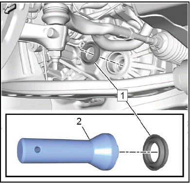
Left Front Wheel Drive Shaft Oil Seal (1) - Install NEW - Use the special tool: DT-446 Installer (2).
2. Front Wheel Drive Half Shaft- Left Side - Install - Refer to Front Wheel Drive Half Shaft Replacement - Left Side.
3. Lower the vehicle.
CONTROL VALVE BODY COVER REPLACEMENT
Special Tools
EN-37228 Separating Tool
Equivalent regional tools: Refer to Special Tools
Removal Procedure
1. Raise and support the vehicle. Lifting and Jacking the Vehicle.
2. Drain the transmission fluid. Transmission Fluid Drain and Fill.
3. Front Compartment Air Deflector - Remove Front Compartment Air Deflector Replacement.
4.
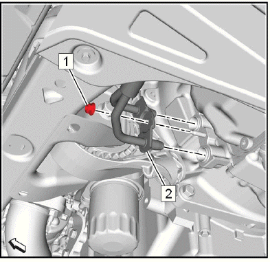
Transmission Fluid Cooler Pipe Nut (1) - Remove.
5. Transmission Fluid Cooler Inlet and Outlet Pipe (2) @Transmission - Disconnect.
6. Transmission Fluid Cooler Inlet and Outlet Pipe - Position aside.
7.
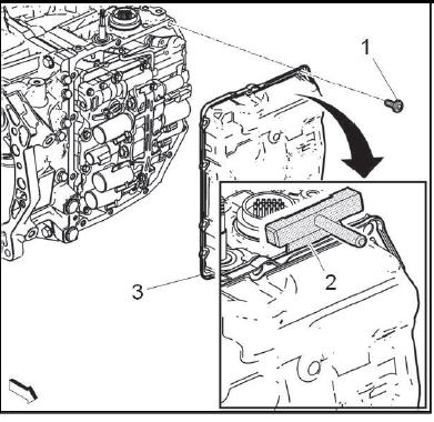
Control Valve Body Cover Bolt (1) - Remove[13x].
8. Slide the EN-37228 separating tool (2) around the perimeter of the control valve body cover to break the sealant.
9. Control Valve Body Cover (3) - Remove.
Installation Procedure
1. Clean all sealing surfaces.
2. Apply a bead of sealant to the perimeter of the sealing surface on the transmission case: Refer to Adhesives, Fluids, Lubricants, and Sealers for the correct type of sealant.
3. Control Valve Body Cover (2) - Install.
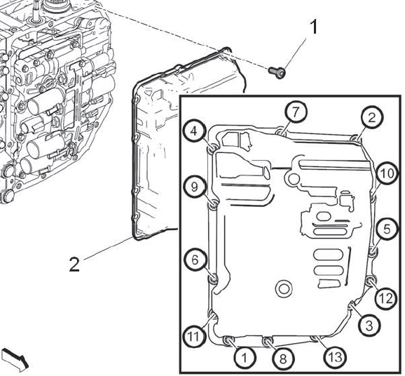
Fig. 1: Automatic Transmission Valve Body Bolts Tightening Sequence
4. Control Valve Body Cover Bolt (1) - Install and tighten[13x]13N.m (115 lb in) - Tighten in the sequence shown.
5.

Transmission Fluid Cooler Inlet and Outlet Pipe (2) - Reposition.
6. Transmission Fluid Cooler Inlet and Outlet Pipe@Transmission - Connect.
7. Transmission Fluid Cooler Pipe Nut (1) - Install and tighten10N.m (89 lb in).
8. Front Compartment Air Deflector - Install Front Compartment Air Deflector Replacement.
9. Lower the vehicle.
10. Fill the transmission to the proper level with NEW transmission fluid. Transmission Fluid Drain and Fill.
11. Reset the learned values of the transmission control module. Learned Values Reset.
CONTROL VALVE BODY REPLACEMENT
Removal Procedure
1. Transmission Control Module - Remove - Refer to Transmission Control Module Replacement.
2. Drain the transmission fluid. Transmission Fluid Drain and Fill.
3. Control Valve Body Cover - Remove - Refer to Control Valve Body Cover Replacement.
NOTE: Note the position and color of each electrical connector.
4. Wiring Harness Wire - Remove - Refer to Wiring Harness Wire Replacement.
5.
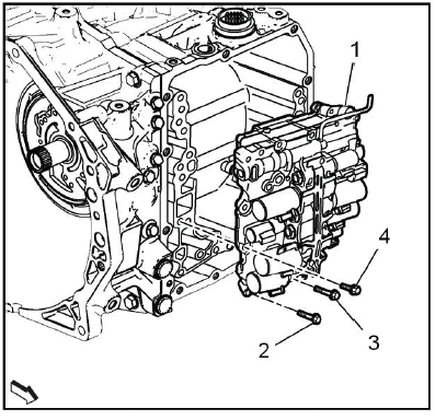
NOTE: The control valve body bolts have different lengths. Note the position of every bolt.
Control Valve Body Bolt (2, 3, 4) - Remove[8x]
- (2) = M6 x 31 [2x]
- (3) = M6 x 51 [1x]
- (4) = M6 x 21 [5x]
6. Control Valve Body (1) - Remove.
Installation Procedure
1. Control Valve Body (1) - Install.
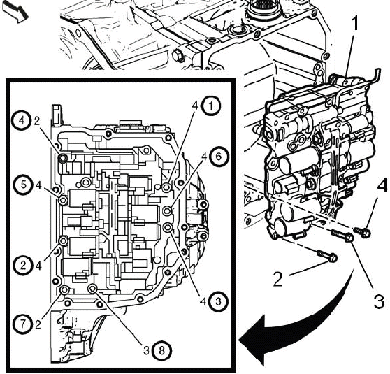
Fig. 2: Automatic Transmission Valve Body Control Unit Bolts Tightening
Sequence
Control Valve Body (1) - Install.
2. Control Valve Body Bolt (2, 3, 4) - Install and tighten[8x]10N.m (89 lb in) - Tighten the bolts in the sequence shown.
NOTE: The control valve body bolts have different lengths. Note the position of every bolt.
- (2) = M6 x 31 [2x]
- (3) = M6 x 51 [1x]
- (4) = M6 x 21 [5x]
3. Wiring Harness Wire - Install - Refer to Wiring Harness Wire Replacement.
4. Control Valve Body Cover - Install - Refer to Control Valve Body Cover Replacement.
5. Transmission Control Module - Install - Refer to Transmission Control Module Replacement.
6. Fill the transmission to the proper level with NEW transmission fluid. Transmission Fluid Drain and Fill.
7. Reset the learned values of the transmission control module. Learned Values Reset.
8. Learn the gear selector neutral position. Gear Selector -N- Position Learn.
READ NEXT:
 Wiring Harness Wire Replacement
Removal Procedure
1. Transmission Control Module - Remove - Refer to Transmission Control
Module Replacement.
2. Drain the transmission fluid. Transmission Fluid Drain and Fill.
3. Control Valve Bo
Torque Converter Assembly Removal
Torque Converter
TORQUE CONVERTER FLUID SEAL REMOVAL
Torque Converter Fluid Seal
Special Tools
EN-45000 Seal Remover
Equivalent regional tools: Refer to Special Tools
TRANSMISSION CONTROL
SEE MORE:
DTC B2745
Diagnostic Instructions
Perform the Diagnostic System Check - Vehicle prior to using this
diagnostic procedure.
Review Strategy Based Diagnosis for an overview of the diagnostic
approach.
Diagnostic Procedure Instructions provides an overview of each
diagnostic category.
DTC Descriptor
DT
DTC P0513
Diagnostic Instructions
Perform the Diagnostic System Check - Vehicle prior to using this
diagnostic procedure.
Review Strategy Based Diagnosis for an overview of the diagnostic
approach.
Diagnostic Procedure Instructions provides an overview of each
diagnostic category.
DTC Descriptor
DT
