Buick Regal: Wiring Harness Wire Replacement
Removal Procedure
1. Transmission Control Module - Remove - Refer to Transmission Control Module Replacement.
2. Drain the transmission fluid. Transmission Fluid Drain and Fill.
3. Control Valve Body Cover - Remove - Refer to Control Valve Body Cover Replacement.
4.
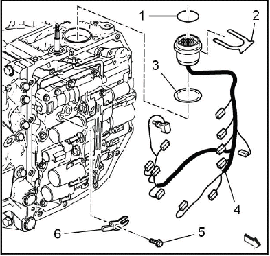
NOTE: Note the position and color of each electrical connector.
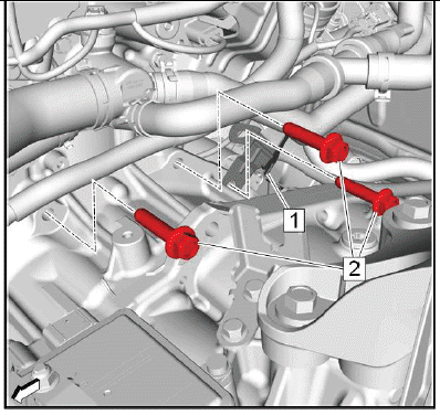
Wiring Harness - Remove
- Automatic Transmission Fluid Temperature Sensor Bolt (5) - Remove
- Automatic Transmission Fluid Temperature Sensor Clip (6) - Remove
- Automatic Transmission Wiring Harness Retainer (2) - Remove
- Disconnect all wiring harness connectors from the control valve body
- Wiring Harness Wire (4) - Remove
- Transmission Gasket (3) - Remove and DISCARD
- Automatic Transmission Wiring Connector Seal (1) - Remove and DISCARD
Installation Procedure
1.
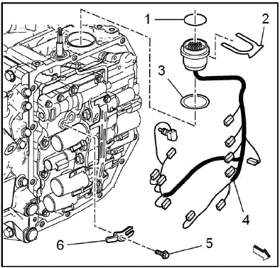
Wiring Harness - Install
- Automatic Transmission Wiring Connector Seal (1) - Install NEW
- Transmission Gasket (3) - Install NEW
- Wiring Harness Wire (4) - Install
- Connect all wiring harness connectors to the control valve body
- Automatic Transmission Wiring Harness Retainer (2) - Install
- Automatic Transmission Fluid Temperature Sensor Clip (6) - Install
- Automatic Transmission Fluid Temperature Sensor Bolt (5) - Install and tighten7N.m (62 lb in)
2. Control Valve Body Cover - Install - Refer to Control Valve Body Cover Replacement.
3. Transmission Control Module - Install - Refer to Transmission Control Module Replacement.
4. Fill the transmission to the proper level with NEW transmission fluid. Transmission Fluid Drain and Fill.
5. Reset the learned values of the transmission control module. Learned Values Reset.
6. Learn the gear selector neutral position. Gear Selector -N- Position Learn.
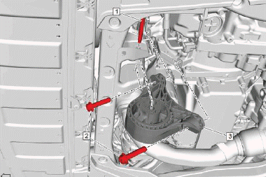
TRANSMISSION REAR MOUNT BRACKET REPLACEMENT
Preliminary Procedure
Refer to Transmission Rear Mount Replacement.
- Transmission Rear Mount Bracket Bolt [3x]
CAUTION: Refer to Fastener Caution
CAUTION: Refer to Torque-to-Yield Fastener Caution
Procedure
Install NEW bolts. - Do NOT reuse the old bolt.
Tighten
- First Pass:100N.m (74 lb ft)
- Final Pass:60 - 75 degrees
Special Tools
EN-45059 Angle Meter
Equivalent regional tools: Refer to Special Tools
- Transmission Rear Mount Bracket
TRANSMISSION REAR MOUNT REPLACEMENT
Special Tools
- EN-45059 Angle Meter
Equivalent regional tools: Refer to Special Tools
Removal Procedure
1. Raise and support the vehicle. Lifting and Jacking the Vehicle.
2. Charge Air Cooler Outlet Air Tube - Remove - Refer to Charge Air Cooler Outlet Air Tube Replacement.
3. Exhaust Front Pipe - Remove - Refer to Exhaust Front Pipe Replacement (FWD LGX) Refer to Exhaust Front Pipe Replacement (LTG) Refer to Exhaust Front Pipe Replacement (AWD LGX).
4. Propeller Shaft - Remove - Refer to Propeller Shaft Replacement.
5. Transmission Front Mount - Remove - Refer to Transmission Front Mount Replacement.
6. Charge Air Cooler Inlet Air Tube - Remove - Refer to Charge Air Cooler Inlet Air Tube Replacement.
7. Front Compartment Air Deflector - Remove - Refer to Front Compartment Air Deflector Replacement.
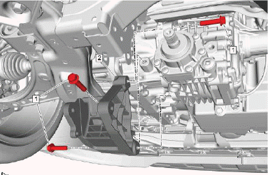
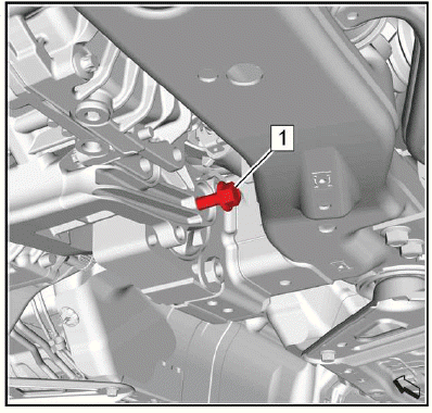
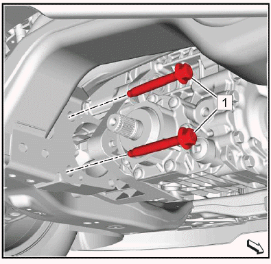
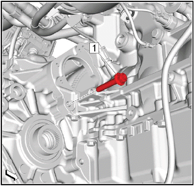
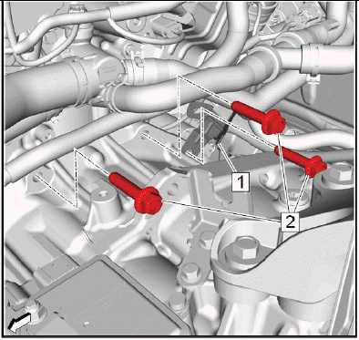
8.
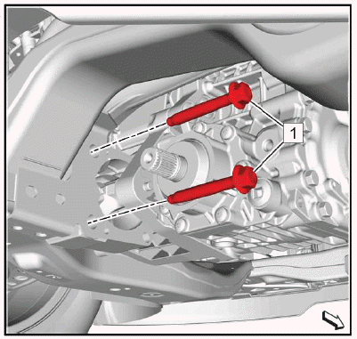
Remove and DISCARD the 2 transmission rear mount bolts (1).
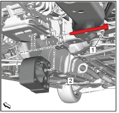
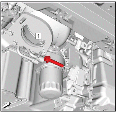
9.
Loosen the transmission rear mount through bolt (1).
NOTE: A second technician is required.
10. Push the engine / transmission unit far enough forward to get space for the removal of the transmission rear mount through bolt.
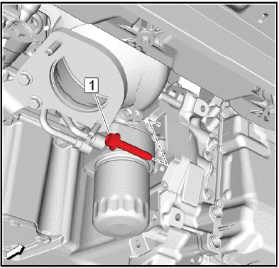
11.
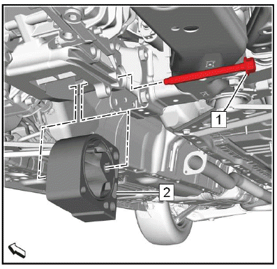
Remove the transmission rear mount through bolt (1).
12. Transmission Rear Mount (2) - Remove.
13. Release the engine / transmission unit to bring it into original position.
Installation Procedure
NOTE: A second technician is required.
1. Push the engine / transmission unit far enough forward to get space for the installation of the transmission rear mount through bolt.
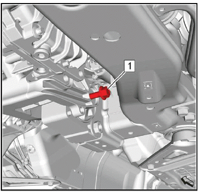
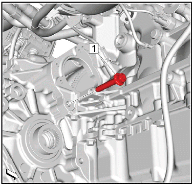
2.
Transmission Rear Mount (2) - Install.
3. Install the transmission rear mount through bolt (1).
4. Release the engine / transmission unit to bring it into original position.
5.
CAUTION: Refer to Fastener Caution.
Tighten the transmission rear mount through bolt (1) to 100N.m (74 lb ft).
6.
CAUTION: Refer to Torque-to-Yield Fastener Caution.
Install the 2 NEW transmission rear mount bolts (1) and tighten a first pass to 100N.m (74 lb ft).
7. Tighten the 2 NEW transmission rear mount bolts a final pass to 120 - 135 degrees, using the EN-45059 meter.
8. Front Compartment Air Deflector - Install - Refer to Front Compartment Air Deflector Replacement.
9. Charge Air Cooler Inlet Air Tube - Remove - Refer to Charge Air Cooler Inlet Air Tube Replacement.
10. Transmission Front Mount - Install - Refer to Transmission Front Mount Replacement.
11. Propeller Shaft - Install - Refer to Propeller Shaft Replacement.
12. Exhaust Front Pipe - Install - Refer to Exhaust Front Pipe Replacement (FWD LGX) Refer to Exhaust Front Pipe Replacement (LTG) Refer to Exhaust Front Pipe Replacement (AWD LGX).
13. Charge Air Cooler Outlet Air Tube - Remove - Refer to Charge Air Cooler Outlet Air Tube Replacement.
14. Lower the vehicle.
TRANSMISSION FRONT MOUNT REPLACEMENT
Preliminary Procedure
Refer to Lifting and Jacking the Vehicle.
- Transmission Front Mount Through Bolt
CAUTION: Refer to Fastener Caution
Tighten 100N.m (74 lb ft)
- Transmission Front Mount to Transmission Bolt [2x]
Tighten 100N.m (74 lb ft)
- Transmission Front Mount
TRANSMISSION REPLACEMENT
Special Tools
- EN-45059 Angle Meter
- EN-51007 Engine Support Fixture
Equivalent regional tools: Refer to Special Tools
Removal Procedure
1. Battery Tray - Remove - Refer to Battery Tray Replacement.
2. Charge Air Cooler Outlet Air Tube - Remove - Refer to Charge Air Cooler Outlet Air Tube Replacement.
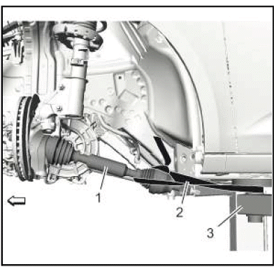
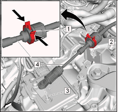
3.
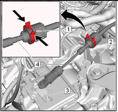
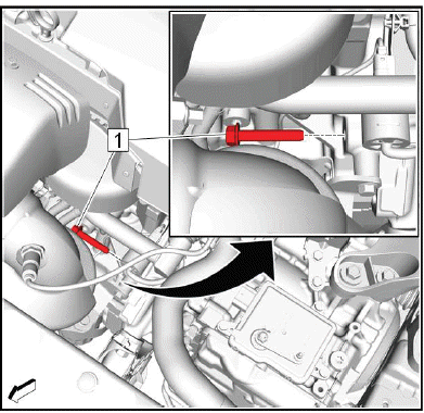
Range Selector Lever Cable (4) @Range Selector Lever Cable Lever (3) - Remove.
4. Range Selector Lever Cable@Transmission Range Selector Lever Cable Bracket (2) - Remove.
Push (arrows) the latches of the retainer (1) to release the range selector lever cable from the bracket.
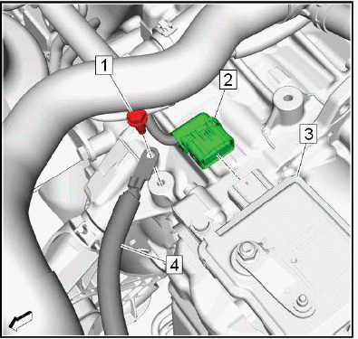
5.
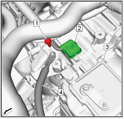
Electrical Connector (2) @Transmission Control Module (3) - Disconnect.
6. Battery Negative Cable Ground Bolt (1) - Remove.
7. Battery Negative Cable (4) - Position aside.
8.
NOTE: The graphic is shown without generator positive cable for the sake of clarity.
Remove the 3 transmission upper bolts (2).
9. Generator and Starter Cable Bracket (1) - Position aside.
10.
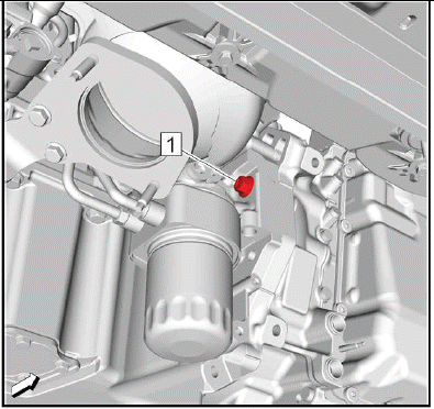
Remove the transmission front upper bolt (1).
11. Raise and support the vehicle. Lifting and Jacking the Vehicle.
12. Transmission Fluid - Drain - Refer to Transmission Fluid Drain and Fill.
13. Exhaust Front Pipe - Remove - Refer to Exhaust Front Pipe Replacement (FWD LGX) Refer to Exhaust Front Pipe Replacement (LTG) Refer to Exhaust Front Pipe Replacement (AWD LGX).
14. Propeller Shaft - Remove - Refer to Propeller Shaft Replacement.
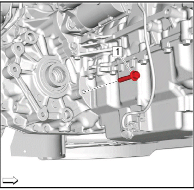
15.
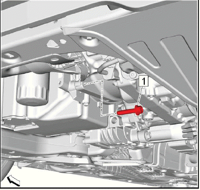
Remove the transmission lower bolt (1).
16. Drivetrain and Front Suspension Cradle - Remove - Refer to Drivetrain and Front Suspension Cradle Replacement (LGX) Refer to Drivetrain and Front Suspension Cradle Replacement (LTG).
17. Transmission Front Mount - Remove - Refer to Transmission Front Mount Replacement.
18. Transmission Rear Mount Bracket - Remove - Refer to Transmission Rear Mount Bracket Replacement.
19. Transmission Fluid Cooler Inlet and Outlet Pipe@Transmission - Remove - Refer to Transmission Fluid Cooler Inlet and Outlet Pipe Replacement (AF50-8) Plug and/or cap the pipes and transmission to prevent contamination.
20. Oil Pump Flow Control Valve Heat Shield - Remove - Refer to Oil Pump Flow Control Valve Heat Shield Replacement.
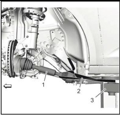
21. Front Wheel Drive Half Shaft- Right Side@Transfer Case - Disconnect - Refer to Front Wheel Drive Half Shaft Replacement - Right Side (AWD) Refer to Front Wheel Drive Half Shaft Replacement - Right Side (FWD).
22.
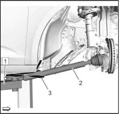
Secure the right drive shaft (2) to the hoist (1), using a lashing strap (3).
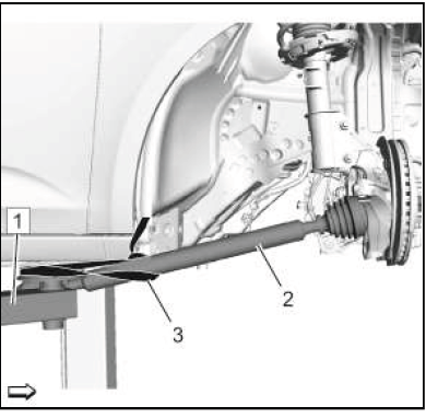
23. Front Wheel Drive Half Shaft- Left Side@Transmission - Disconnect - Refer to Front Wheel Drive Half Shaft Replacement - Left Side.
24.
Secure the left drive shaft (1) to the hoist (3), using a lashing strap (2).
25. Power Transfer Unit Case - Remove - Refer to Power Transfer Unit Case Replacement.
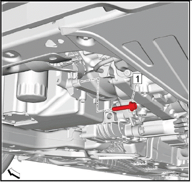
26.
Remove the transmission lower bolt (1).
27. Starter - Remove - Refer to Starter Replacement (2.0L LTG) Refer to Starter Replacement (3.6L LGX).
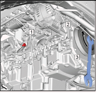
28.
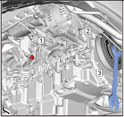
Torque Converter@Flex Plate - Loosen
- Turn the engine at the crankshaft balancer (2) clockwise (arrow) with a suitable tool (3), until a torque converter bolt (1) shows up.
- Remove and DISCARD the first torque converter bolt.
- Turn the engine at the crankshaft balancer clockwise 60 degrees.
- Remove and DISCARD the next torque converter bolt.
- Repeat the previous 2 steps until the sixth torque converter bolt is removed.
29. Lower the vehicle.
30. Transmission Vent Hose - Remove - Refer to Vent Hose Replacement.
31. Engine Support Fixture - Install - Refer to Engine Support Fixture.
32. Apply tension to the hooks of the EN-51007 fixture.
33.
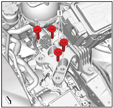
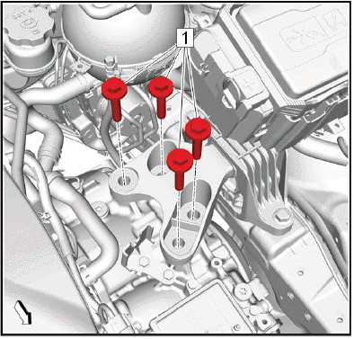
34. Remove and DISCARD the 4 transmission mount to transmission bolts (1).
35. Lower the engine/transmission unit about 5.5cm (2.16in), using the EN-51007 fixture.
36. Raise the vehicle.
37. Support the transmission with a suitable jack.
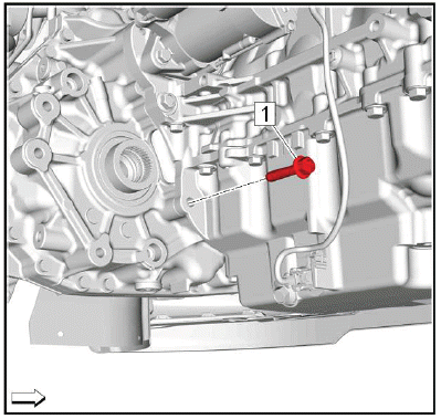
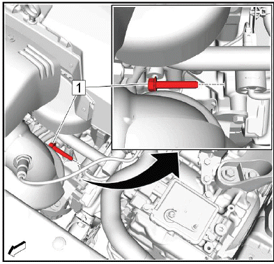
38.
Remove the transmission rear bolt (1).
39.
NOTE: This is the last transmission bolt.
Remove the transmission front lower bolt (1).
NOTE: A second technician is required.
40. Separate the transmission from the engine.
41. Lower the transmission jack far enough to remove the transmission.
Installation Procedure
1. Transfer components as necessary.
2. If the removed transmission will be reinstalled, clean the threads of the torque converter.
NOTE: A second technician is required.
3. Raise the transmission with the transmission jack and position the transmission to the engine.
4.
CAUTION: Refer to Fastener Caution
Install the transmission front lower bolt (1) and tighten a first pass to 10N.m (89 lb in), in order to align the transmission and the engine flush.
5.
Install the transmission rear bolt (1) and tighten to 58N.m (43 lb ft).
6.
Tighten the transmission front lower bolt a final pass to 58N.m (43 lb ft).
7. Remove the transmission jack.
8. Lower the vehicle.
9. Raise the engine/transmission unit into original position, using the EN-51007 fixture.
10.
CAUTION: Refer to Torque-to-Yield Fastener Caution.
Install 4 NEW transmission mount to transmission bolts (1) and tighten a first pass to 100N.m (74 lb ft).
11. Tighten the 4 NEW transmission mount to transmission bolts (1) a final pass to 60 - 75 degrees, using the EN- 45059 meter.
12. Engine Support Fixture - Remove - Refer to Engine Support Fixture.
13. Transmission Vent Hose - Install - Refer to Vent Hose Replacement.
14. Raise the vehicle.
15.
Torque Converter@Flex Plate - Install.
- Turn the engine at the crankshaft balancer (2) clockwise (arrow) with a suitable tool (3), until a torque converter thread shows up.
NOTE: Service may offer bolts without microencapsulated thread locking adhesive. If this is the case, apply thread locking adhesive to the bolt.
- Install the first NEW torque converter bolt (1) and tighten to 60N.m (44 lb ft).
- Turn the engine at the crankshaft balancer clockwise 60 degrees.
- Install the next NEW torque converter bolt and tighten to 60N.m (44 lb ft).
- Repeat the previous 2 steps until the sixth torque converter bolt is installed.
16. Starter - Install - Refer to Starter Replacement (2.0L LTG) Refer to Starter Replacement (3.6L LGX).
17.
Install the transmission lower bolt (1) and tighten to 58N.m (43 lb ft).
18. Power Transfer Unit Case - Install - Refer to Power Transfer Unit Case Replacement.
19.
Remove the left drive shaft (1) from the hoist (3).
20. Front Wheel Drive Half Shaft- Left Side@Transmission - Connect - Refer to Front Wheel Drive Half Shaft Replacement - Left Side.
21.
Remove the right drive shaft (2) from the hoist (1).
22. Front Wheel Drive Half Shaft- Right Side@Transfer Case - Connect - Refer to Front Wheel Drive Half Shaft Replacement - Right Side (AWD) Refer to Front Wheel Drive Half Shaft Replacement - Right Side (FWD).
23. Oil Pump Flow Control Valve Heat Shield - Install - Refer to Oil Pump Flow Control Valve Heat Shield Replacement.
24. Transmission Fluid Cooler Inlet and Outlet Pipe@Transmission - Install - Refer to Transmission Fluid Cooler Inlet and Outlet Pipe Replacement (AF50-8).
25. Transmission Rear Mount Bracket - Install - Refer to Transmission Rear Mount Bracket Replacement.
26. Transmission Front Mount - Install - Refer to Transmission Front Mount Replacement.
27. Drivetrain and Front Suspension Cradle - Install - Refer to Drivetrain and Front Suspension Cradle Replacement (LGX) Refer to Drivetrain and Front Suspension Cradle Replacement (LTG).
28.
Install the transmission lower bolt (1) and tighten to 58N.m (43 lb ft).
29. Propeller Shaft - Install - Refer to Propeller Shaft Replacement.
30. Exhaust Front Pipe - Install - Refer to Exhaust Front Pipe Replacement (FWD LGX) Refer to Exhaust Front Pipe Replacement (LTG) Refer to Exhaust Front Pipe Replacement (AWD LGX).
31. Lower the vehicle.
32.
Install the transmission front upper bolt (1) and tighten to 58N.m (43 lb ft).
33.
NOTE: The graphic is shown without generator positive cable for the sake of clarity.
Generator and Starter Cable Bracket (1) - Reposition.
34. Install the 3 transmission upper bolts (2) and tighten to 58N.m (43 lb ft).
35.
Battery Negative Cable (4) - Reposition.
36. Battery Negative Cable Ground Bolt (1) - Install and tighten22N.m (16 lb ft).
37. Electrical Connector (2) @Transmission Control Module (3) - Connect.
38.
Range Selector Lever Cable (4) @Transmission Range Selector Lever Cable Bracket (2) - Install.
Push the range selector lever cable into the bracket. The retainer (1) must engage noticeable.
39. Range Selector Lever Cable@Range Selector Lever Cable Lever (3) - Install.
40. Range Selector Lever Cable - Adjust - Refer to Range Selector Lever Cable Adjustment.
41. Charge Air Cooler Outlet Air Tube - Install - Refer to Charge Air Cooler Outlet Air Tube Replacement.
42. Battery Tray - Install - Refer to Battery Tray Replacement.
43. Transmission Fluid - Fill - Refer to Transmission Fluid Drain and Fill.
44. Run all necessary programming and setup procedures. Control Module: References.
45. Road test the vehicle.
READ NEXT:
 Torque Converter Assembly Removal
Torque Converter
TORQUE CONVERTER FLUID SEAL REMOVAL
Torque Converter Fluid Seal
Special Tools
EN-45000 Seal Remover
Equivalent regional tools: Refer to Special Tools
TRANSMISSION CONTROL
Manual Shift Detent Lever and Park Pawl Removal
Park Components Removal
Park Components Removal
Manual Shift Detent Bolt
Automatic Transmission Control Lever Detent Spring
Manual Shift Detent Lever Spring
Park Pawl Lockout Pin
Park Pawl Shaf
SEE MORE:
Tire Pressure Monitor
System
The Tire Pressure Monitor System
(TPMS) uses radio and sensor
technology to check tire pressure
levels. The TPMS sensors monitor
the air pressure in your tires and
transmit tire pressure readings to a
receiver located in the vehicle.
Each tire, including the spare (if
provided), should be checked
m
DTC B3843
Diagnostic Instructions
Perform the Diagnostic System Check - Vehicle prior to using this
diagnostic procedure.
Review Strategy Based Diagnosis for an overview of the diagnostic
approach.
Diagnostic Procedure Instructions provides an overview of each
diagnostic category.
DTC Descriptors
D
