Buick Regal: Instrument Panel Compartment Door Lock Cylinder Coding
The internal lock cylinder only uses 4 of the 8 cut positions, 5 - 8. The tumbler positions are on both sides, are not self-retaining, and are not snap in.
1.
NOTE: All lock cylinders for side milled keys have right and left tumblers.
The location of the tooth of the tumbler determines whether it is right of left. Illustrations in this procedure show the right tumblers on the top and the left tumblers on the bottom. All tumblers are marked 1R, 1L, 2R, or 2L. The number being cut depth and the letter meaning right or left.
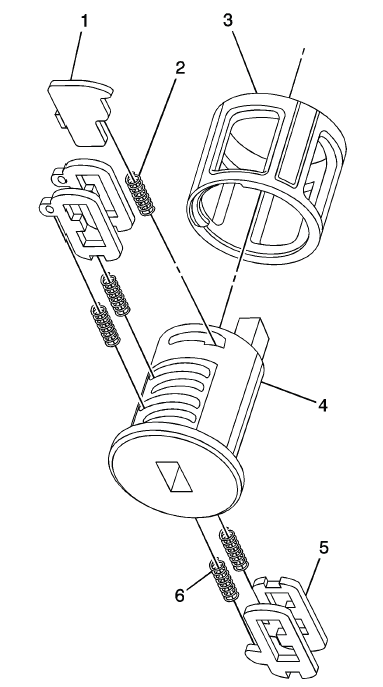
Hold the instrument panel (I/P) cylinder assembly (4) so the side with the tumbler spring pocket located closest to the head of the cylinder is facing up. This side of the cylinder uses left tumbler.
2. Insert the tumbler spring (6) into each of the 2 spring pockets of the cylinder assembly. This side uses left tumblers.
3. The first tumbler (5) to be loaded (closest to the head of the cylinder) will be the fifth key cut position, which is the fifth number in the key code. Install the tumbler in the slot over the spring.
Install the remaining tumblers following the key code and same process, pressing the tumblers in place until they are secure.
4. Rotate the cylinder assembly. Insert the tumbler spring (6) into each of the spring pockets of the cylinder assembly. This side uses right tumblers.
5. The first tumbler (5) to be loaded will be the sixth key cut position, the sixth number in the key code. Install the first tumbler in the slot over the spring. Install the remaining tumblers following the key code and same process, pressing the tumblers in place until they are secure.
6. Inspect for correct loading of the tumblers by inserting the key into the cylinder. All tumblers should drop flush with the lock cylinder body diameter.
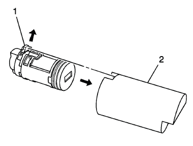
7. Insert the sleeve (3) into the cylinder, the inner sleeve slot must be oriented to the head cylinder side. Rotate the sleeve until the slot match with the tab.
8. Insert the retainer spring (2) into the pocket and the tumbler retainer (1) over the spring. Make sure the tumbler retainer is properly seated and cannot pull out.
9. Lightly lubricate the outside surface in the tumbler area of the lock body and down the key slot using the provided grease. Insert and extract the key 5 times to lubricate the keyway.
10. When the key is removed, the lock should stay together.
11. Insert the key and function the lock 3 times to distribute the grease inside the sleeve.
12. Verify the key position for inserting the lock into the I/P compartment door.
FRONT SIDE DOOR LOCK CYLINDER CODING (FREE WHEELING)
Special Tools
BO-49753 Assembly Tool
The door lock cylinder uses 8 of the 8 cut positions. The tumbler positions are staggered from side to side, 4 on one side and 4 on the other, are not self-retaining, and are not snap in.
NOTE: All lock cylinders for side milled keys have right and left tumblers.
The location of the tooth of the tumbler determines whether it is right of left. Illustrations in this procedure show the right tumblers on the top and the left tumblers on the bottom. All tumblers are marked 1R, 1L, 2R, or 2L. The number being cut depth and the letter meaning right or left.
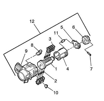
1. Hold the door lock cylinder (1) so the side with the 4 tumbler spring pockets faces up, pocket nearest to the cylinder head.
2. Insert the tumbler springs (2) into the 4 spring pockets. This side uses left tumblers.
3. Install the tumbler (3) for key cut position one in the slot nearest to the front of the lock cylinder.
Install the remaining tumblers, key cut positions 3, 5, and 7, following the key code and same process. Press the tumblers in place until they are secure.
4. Check the correct loading of the tumblers by inserting the key into the cylinder. All tumblers should be flush with the lock cylinder body.
5. Turn the cylinder so the side with the 4 tumbler spring wells faces up. This side uses right tumblers.
6. Insert the tumbler springs into the 4 spring pockets.
7. The first tumbler closest to the front of the lock cylinder to be loaded will be the second key cut position, the second number in the key code. Install the remaining tumblers for the key cut positions 4, 6, and 8. Press the tumblers in place until they are secure.
8. Check the correct loading of the tumblers by inserting the key into the cylinder. All tumblers should be flush with the lock cylinder body.
9. Insert the key and lightly lubricate the cylinder body diameter and tumbler surfaces and a small amount in the head of the cylinder using the supplied grease.
10. Insert the sleeve (4) onto the cylinder assembly.
11. Insert the clutch (5) and driver (6) onto the cylinder (1).
12.
Load the cylinder into the BO-49753 assembly tool so that the clutch (1) indexes with the notch in the opening of the tool (2).
13.
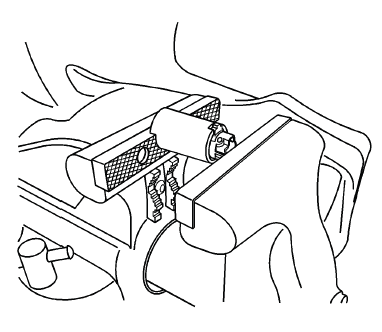
Load the assembly tool with the lock cylinder into a vice and tighten the vice ONLY enough to hold the tool and lock the cylinder in place.
14.
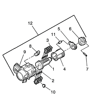
Insert the roll pin (7) into the driver (6) and install it using a 1/16 inch pin punch.
15. Insert the buffer (8) in the case (9), verify the buffer is properly seated.
16. Install the free wheel pin (11) in the sleeve (4) and clutch (5) and insert the assembly into the case (9).
17. With the lock cylinder assembly installed in the case (9), install the retainer (10) and stake the retainer in place using a small punch and hammer to peen the case material onto the exposed ends of the installed retainer (10).
18. Insert the key into the lock and function the lock to check for proper assembly and smooth operation.
FRONT SIDE DOOR LOCK CYLINDER CODING (NON FREE WHEELING)
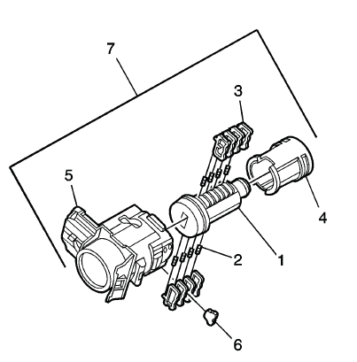
The door lock cylinder uses 8 of the 8 cut positions. The tumbler positions are staggered from side to side, 4 on one side and 4 on the other, are not self-retaining, and are not snap in.
NOTE: All lock cylinders for side milled keys have right and left tumblers.
The location of the tooth of the tumbler determines whether it is right of left. Illustrations in this procedure show the right tumblers on the top and the left tumblers on the bottom. All tumblers are marked 1R, 1L, 2R, or 2L. The number being cut depth and the letter meaning right or left.
1. Hold the door lock cylinder (1) so the side with the 4 tumbler spring pockets faces up, pocket nearest to the cylinder head.
2. Insert the tumbler springs (2) into the 4 spring pockets. This side uses left tumblers.
3. Install the tumbler (3) for key cut position one in the slot nearest to the front of the lock cylinder.
Install the remaining tumblers, key cut positions 3, 5, and 7, following the key code and same process. Press the tumblers in place until they are secure.
4. Check the correct loading of the tumblers by inserting the key into the cylinder. All tumblers should be flush with the lock cylinder body.
5. Turn the cylinder so the side with the 4 tumbler spring wells faces up. This side uses right tumblers.
6. Insert the tumbler springs into the 4 spring pockets.
7. The first tumbler closest to the front of the lock cylinder to be loaded will be the second key cut position, the second number in the key code. Install the remaining tumblers for the key cut positions 4, 6, and 8. Press the tumblers in place until they are secure.
8. Check the correct loading of the tumblers by inserting the key into the cylinder. All tumblers should be flush with the lock cylinder body.
9. Insert the key and lightly lubricate the cylinder body diameter and tumbler surfaces and a small amount in the head of the cylinder using the supplied grease.
10. Insert the sleeve (4) onto the cylinder assembly.
11. Insert the assembly into the case (5).
12. With the lock cylinder assembly installed in the case (5), install the retainer (6) and stake the retainer in place using a small punch and hammer to peen the case material onto the exposed ends of the installed retainer (6).
13. Insert the key into the lock and function the lock to check for proper assembly and smooth operation.
READ NEXT:
 Lock Cylinder Coding - Ignition
The ignition lock cylinder uses 8 key cut positions, 1 - 8. The ignition
cylinder tumblers (3) are located
on alternate sides of the cylinder (5). They are not snap-in and are not
self-retaining. I
Repair Instructions
VOLATILE MEMORY PROGRAMMING
Electric Window Lifters
Move all the windows to the topmost position and hold the switch pressed down
for 2 seconds.
Sliding Sunroof
Move the sliding roof to the respectiv
SEE MORE:
DTC C0670 or C0675
Diagnostic Instructions
Perform the Diagnostic System Check - Vehicle prior to using this
diagnostic procedure.
Review Strategy Based Diagnosis for an overview of the diagnostic
approach.
Diagnostic Procedure Instructions provides an overview of each
diagnostic category.
DTC Descriptors
D
Cargo Tie-Downs (Wagon)
There is a movable system to
secure items on the load
compartment floor.
Insert the tie-downs into the rails
and press the button while
inserting it.
Press the button on a tie-down and
slide it to the required position. Fold
up the tie-downs to use them.
To remove the cargo tie-downs, fold
them d
