Buick Regal: Rear Suspension Lower Trailing Link Replacement
Removal Procedure
1. Raise and support the vehicle.
2. Remove the rear tire and wheel assembly.
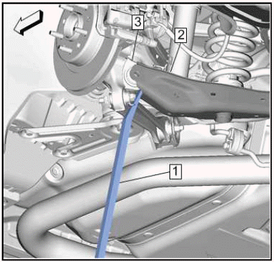
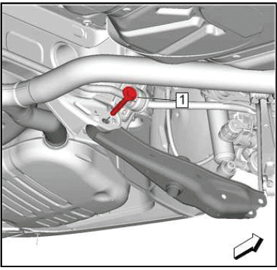
3.
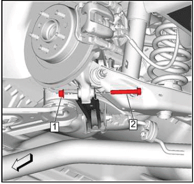
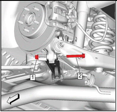
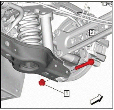
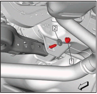
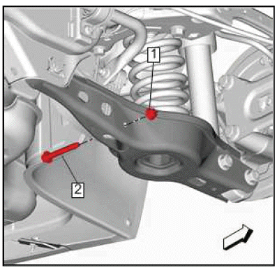
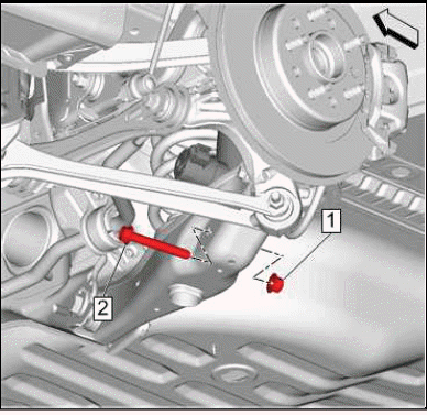
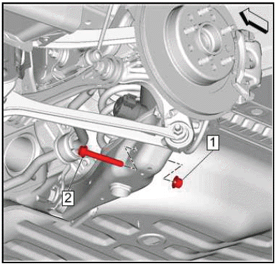
Rear Suspension Trailing Arm Nut(1) - Remove.
4. Rear Suspension Trailing Arm Bolt(2) - Remove and DISCARD.
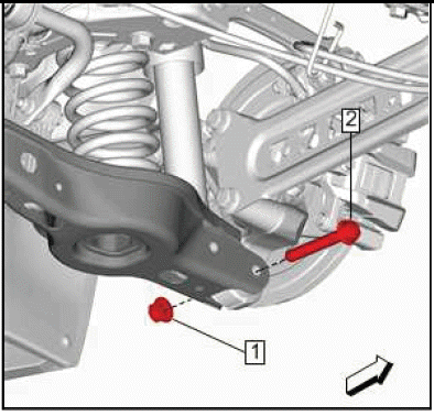
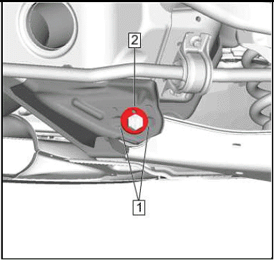
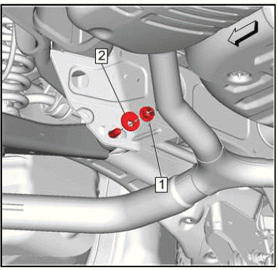
5.
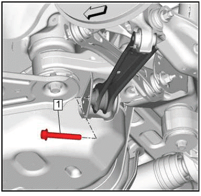
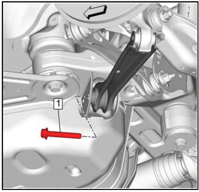
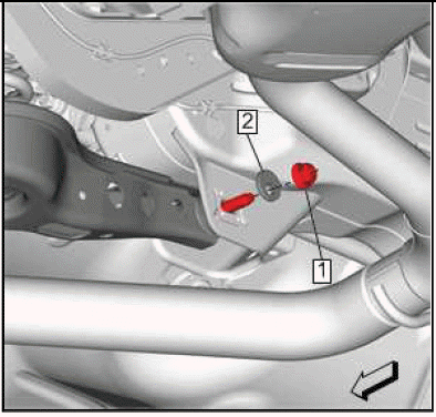
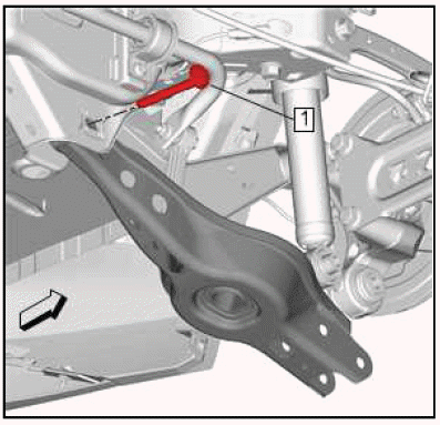
Rear Suspension Trailing Arm Bolt(1) - Remove and DISCARD.
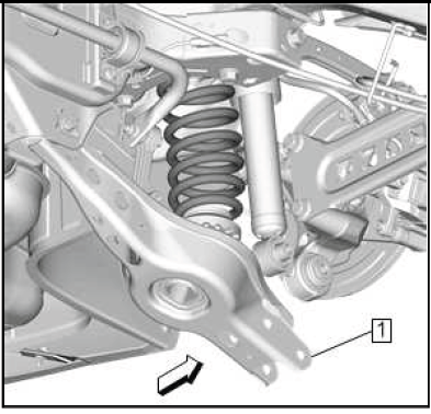
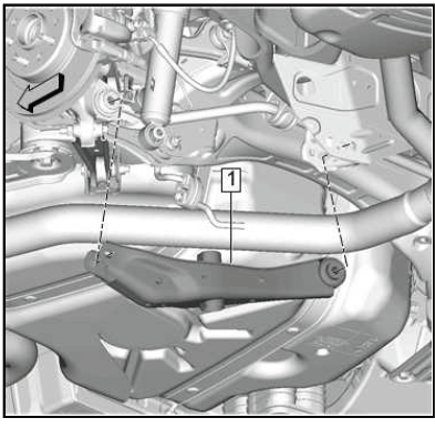
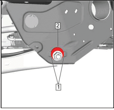
6.
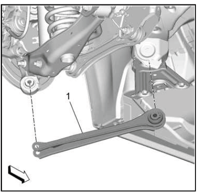
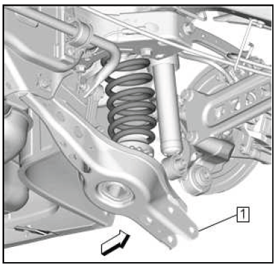
Rear Suspension Lower Trailing Link(1) - Remove.
Installation Procedure
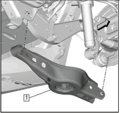
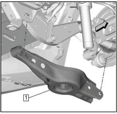
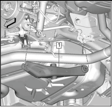
1.
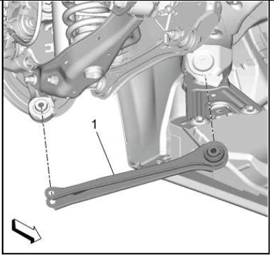
Rear Suspension Lower Trailing Link(1) - Install.
2.
CAUTION: Refer to Fastener Caution.
CAUTION: This vehicle is equipped with torque-to-yield or single use fasteners. Install a NEW torque-to-yield or single use fastener when installing this component.
Failure to replace the torque-to-yield or single use fastener could cause damage to the vehicle or component.
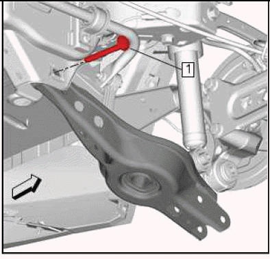
Rear Suspension Trailing Arm Bolt(1) - Install NEW and tighten.
- First Pass: 100 N.m (74 lb ft)
- Final Pass: (90 - 105 degrees)
3.
Rear Suspension Trailing Arm Bolt(2) - Install NEW.
4. Rear Suspension Trailing Arm Nut(1) - Install and hand tighten.
5. Rear Suspension Trailing Arm Bolt(2) - Tighten
- First Pass: 100 N.m (74 lb ft)
- Final Pass: (90 - 105 degrees)
6. Install the rear tire and wheel assembly.
7. Remove the support and lower the vehicle.
LOWER CONTROL ARM REPLACEMENT (FWD)
Removal Procedure
1. Remove the rear tire and wheel assembly.
2. Support the rear suspension lower control arm.
3.
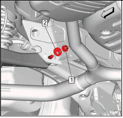
Rear Stabilizer Shaft Link Nut(1) - Remove.
4. Rear Stabilizer Shaft Link Bolt(2) - Remove.
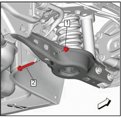
5.
Rear Shock Absorber Nut(1) - Remove.
6. Rear Shock Absorber Bolt(2) - Remove and DISCARD.
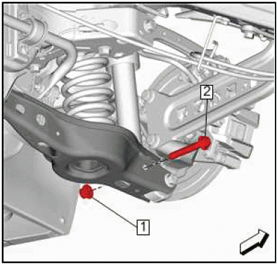
7.
Rear Suspension Lower Control Arm Outer Nut(1) - Remove.
8. Rear Suspension Lower Control Arm Outer Bolt(2) - Remove and DISCARD.
9.
Rear Suspension Lower Control Arm Inner Nut(1) - Remove.
10. Rear Suspension Lower Control Arm Adjust Cam(2) - Remove.
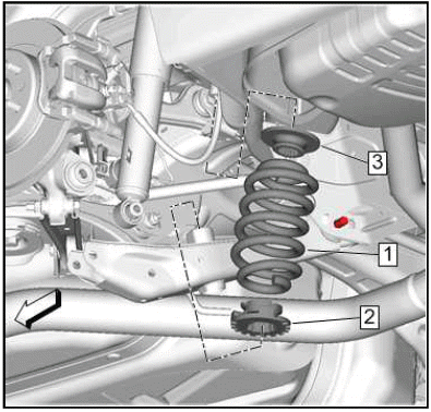
11.
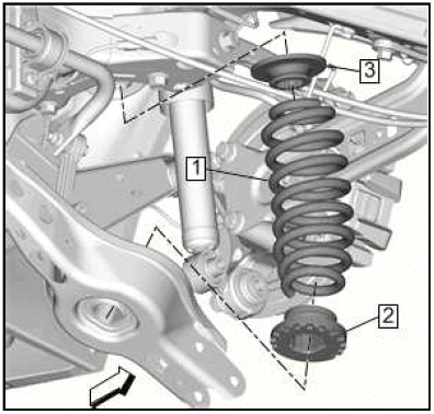
Lower the rear suspension lower control arm (1) to provide clearance for the rear coil spring.
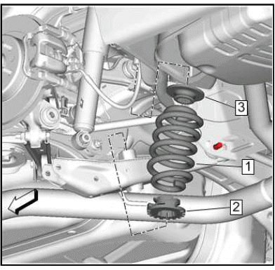
12.
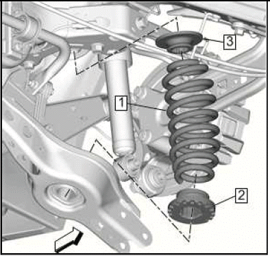
Rear Coil Spring (1) - Remove.
13. Rear Coil Spring Lower Insulator (2) - Remove.
14. Rear Coil Spring Insulator (3) - Remove.
15.
Rear Suspension Lower Control Arm Adjust Bolt(1) - Remove.
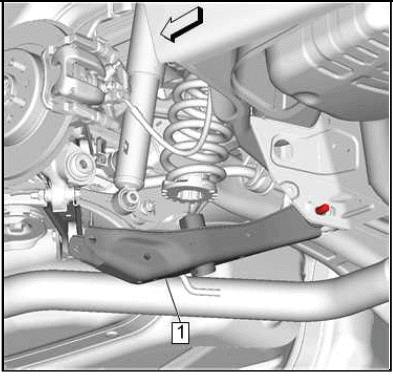
16.
Rear Suspension Lower Control Arm(1) - Remove.
Installation Procedure
1.
Rear Suspension Lower Control Arm(1) - Install.
2.
Rear Suspension Lower Control Arm Adjust Bolt(1) - Install.
3.
Rear Coil Spring Lower Insulator (2) - Install.
4. Rear Coil Spring (1) - Install.
5. Rear Coil Spring Insulator (3) - Install.
6.
Raise the rear suspension lower control arm (1) back into position.
7.
CAUTION: Refer to Fastener Caution.
Rear Suspension Lower Control Arm Adjust Cam(2) - Install.
8. Rear Suspension Lower Control Arm Inner Nut(1) - Install and tighten 90 N.m (66 lb ft).
9.
CAUTION: This vehicle is equipped with torque-to-yield or single use fasteners. Install a NEW torque-to-yield or single use fastener when installing this component.
Failure to replace the torque-to-yield or single use fastener could cause damage to the vehicle or component.
Rear Suspension Lower Control Arm Outer Bolt(2) - Install a NEW bolt.
10. Rear Suspension Lower Control Arm Outer Nut(1) - Install.
Tighten
- First Pass: 160 N.m (118 lb ft)N.m
- Final Pass: (90-105 degrees)
11.

Rear Shock Absorber Bolt(2) - Install a NEW bolt.
12. Rear Shock Absorber Nut(1) - Install.
Tighten
- First Pass: 160 N.m (118 lb ft)N.m
- Final Pass: (90-105 degrees)
13.
Rear Stabilizer Shaft Link Bolt(2) - Install.
14. Rear Stabilizer Shaft Link Nut(1) - Install and tighten 58 N.m (43 lb ft).
15. Remove the support from the rear suspension lower control arm.
16. Install the rear tire and wheel assembly.
17. Verify the rear camber specifications and adjust as necessary.
LOWER CONTROL ARM REPLACEMENT (AWD)
Removal Procedure
1. Raise and support the vehicle.
2. Remove the rear tire and wheel assembly.
3. { If equipped }Wiring Harness@Rear Suspension Lower Control Arm - Separate.
4. Support the rear suspension lower control arm.
5.
Rear Shock Absorber Nut(1) - Remove.
6. Rear Shock Absorber Bolt(2) - Remove and DISCARD.
7.
Rear Suspension Lower Control Arm Outer Nut(1) - Remove.
8. Rear Suspension Lower Control Arm Outer Bolt(2) - Remove and DISCARD.
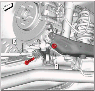
9.
Rear Suspension Lower Control Arm Inner Nut(1) - Remove.
10. Rear Suspension Lower Control Arm Adjust Cam(2) - Remove.
11.
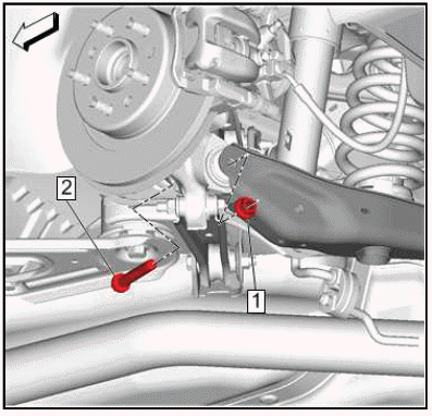
Using a suitable flat bladed tool (1), separate the rear suspension lower control arm (2) from the rear suspension knuckle (3) as shown.
12.

Lower the rear suspension lower control arm (1) to provide clearance for the rear coil spring.
13.
Rear Coil Spring(1) - Remove.
14. Rear Coil Spring Lower Insulator(2) - Remove.
15. Rear Coil Spring Insulator(3) - Remove.
16.

Rear Suspension Lower Control Arm Adjuster Bolt(1) - Remove.
17.
Rear Suspension Lower Control Arm(1) - Remove.
Installation Procedure
1.
Rear Suspension Lower Control Arm(1) - Install.
2.
Rear Suspension Lower Control Arm Adjuster Bolt(1) - Install.
3.
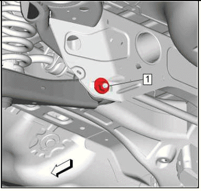
NOTE: Ensure the proper rear suspension lower control arm adjuster bolt and rear suspension lower control arm adjust cam installation and orientation.
Install the rear suspension lower control arm adjuster bolt so the rear suspension lower control arm adjust cam does not overlap the raised structure on the cradle (1), and the rear suspension lower control arm adjust cam scribe marks face 9 and 3 o'clock (2).
4.
Rear Suspension Lower Control Arm Adjust Cam(2) - Install.
5. Rear Suspension Lower Control Arm Inner Nut(1) - Install and hand tighten.
6.
NOTE: Ensure the proper rear suspension lower control arm inner nut and rear suspension lower control arm adjust cam installation and orientation.
Install the rear suspension lower control arm inner nut so the rear suspension lower control arm adjust cam does not overlap the raised structure on the cradle (1), and the cam scribe marks face 9 and 3 o'clock (2).
7.
Rear Coil Spring Insulator(3) - Install.
8. Rear Coil Spring Lower Insulator(2) - Install.
9. Rear Coil Spring(1) - Install.
10.
Raise the rear suspension lower control arm (1) back into position.
11.
CAUTION: This vehicle is equipped with torque-to-yield or single use fasteners. Install a NEW torque-to-yield or single use fastener when installing this component.
Failure to replace the torque-to-yield or single use fastener could cause damage to the vehicle or component.
Rear Suspension Lower Control Arm Outer Bolt(2) - Install NEW.
CAUTION: Refer to Fastener Caution.
12. Rear Suspension Lower Control Arm Outer Nut(1) - Install and tighten.
- First Pass: 150 N.m (111 lb ft)
- Final Pass: (90-105 degrees)
13.
Rear Suspension Lower Control Arm Inner Nut(1) - Tighten 160 N.m (118 lb ft).
14.
Rear Shock Absorber Bolt(2) - Install NEW.
15. Rear Shock Absorber Nut(1) - Install.
16. { If equipped }Wiring Harness@Rear Suspension Lower Control Arm - Install.
17. Remove the support from the rear suspension lower control arm.
18. Install the rear tire and wheel assembly.
19. Remove the support and lower the vehicle.
20. Verify the rear camber specifications and adjust as necessary.
WHEEL STUD REPLACEMENT
Special Tools
CH-43631 Ball Joint Remover
Equivalent regional tools: Special Tools.
Removal Procedure
1. Remove the rear tire and wheel assembly.
2. Rear Wheel Bearing and Hub Assembly - Remove.
3.
Position the wheel bearing and hub assembly in a suitable vise.
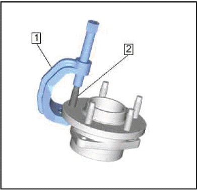
4. Use the CH-43631 ball joint remover (1) to remove and discard the wheel stud (2).
Installation Procedure
1.
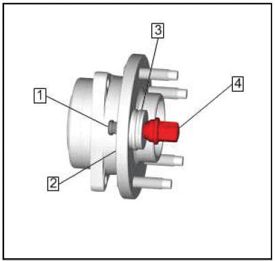
Install the NEW wheel stud (1) into the wheel bearing hub flange (2).
2. Add enough washers (3) in order to draw the stud into the hub flange (2).
3. Install the wheel nut (4) against the washers (3).
4. Tighten the wheel nut (4) until the head of the wheel stud (1) is fully seated against the back of the bearing hub flange (2).
5. Remove the wheel nut (4) and the washers (3).
6. Remove the wheel bearing and hub assembly from the vise.
7. Rear Wheel Bearing and Hub Assembly - Install.
8. Install the rear tire and wheel assembly.
READ NEXT:
 Description and Operation
REAR SUSPENSION DESCRIPTION AND OPERATION
The rear suspension system on this vehicle is of the independent link type.
Rear suspension adjustment is achieved
through adjustable toe links and lower con
Suspension General Diagnosis
SPECIFICATIONS
TRIM HEIGHT SPECIFICATIONS
Trim Height Specifications (P-R Height) - Hatchback
NOTE: For 0% option vehicles add 1 mm to front and rear suspension
values.
For 100% option vehicles subt
Tire Pressure Monitoring System
SPECIFICATIONS
FASTENER SPECIFICATIONS
Reusable Threaded Fastener Tightening Specifications
NOTE:
All fasteners listed in this table can be reused after removal.
SEE MORE:
Vehicle, Engine and Transmission ID and VIN Location, Derivative and
Usage
The vehicle identification number (VIN) plate is the legal identifier of the
vehicle. The VIN plate is
located on the upper left corner of the instrument panel (I/P) and can be seen
through the windshield
from the outside of the vehicle:
2.0L (LTG) Engine ID and VIN Derivative Location
Engine I
DTC P15F6
Diagnostic Instructions
Perform the Diagnostic System Check - Vehicle prior to using this
diagnostic procedure.
Review Strategy Based Diagnosis for an overview of the diagnostic
approach.
Diagnostic Procedure Instructions provides an overview of each
diagnostic category.
DTC Descriptors
D
