Buick Regal: Rear Suspension Upper Lateral Link Replacement (FWD)
Removal Procedure
1. Remove the tire and wheel assembly.
2. { If equipped }Rear Suspension Position Ball Socket @Rear Suspension Upper Lateral Link - Disconnect.
3.
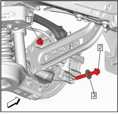
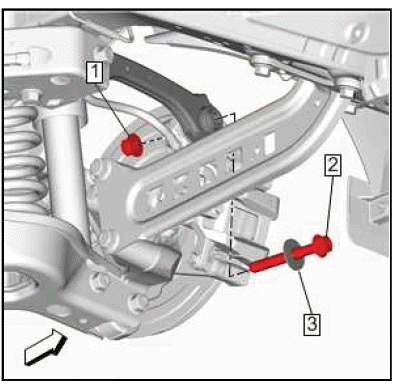
Rear Suspension Upper Lateral Link Nut(1) - Remove.
4. Rear suspension upper lateral link bolt (2) and washer (3) - Remove DISCARD the bolt.
5.
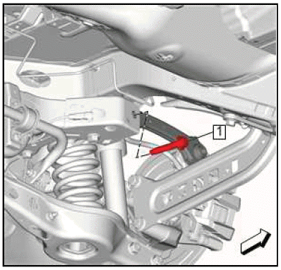
Rear Suspension Upper Lateral Link Inner Bolt(1) - Remove and DISCARD.
6.
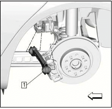
Rear Suspension Upper Lateral Link - Remove.
Installation Procedure
1.
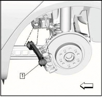
Rear Suspension Upper Lateral Link(1) - Install.
2.
CAUTION: Refer to Fastener Caution.
CAUTION: This vehicle is equipped with torque-to-yield or single use fasteners. Install a NEW torque-to-yield or single use fastener when installing this component.
Failure to replace the torque-to-yield or single use fastener could cause damage to the vehicle or component.
Rear suspension upper lateral link bolt (2) and washer (3) - Install a NEW bolt.
3. Rear Suspension Upper Lateral Link Nut(1) - Install.
Tighten
- First Pass: 160 N.m (118 lb ft)
- Final Pass: (90-105 degrees)
4.
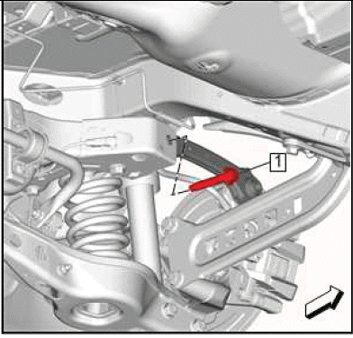
Rear Suspension Upper Lateral Link Inner Bolt(1) - Install a NEW bolt.
Tighten
- First Pass: 160 N.m (118 lb ft)
- Final Pass: (90-105 degrees)
5. { If equipped }Rear Suspension Position Ball Socket @Rear Suspension Upper Lateral Link - Connect.
6. Lower the vehicle.
REAR SUSPENSION UPPER LATERAL LINK REPLACEMENT (AWD)
Removal Procedure
1. Raise and support the vehicle.
2. Lower the rear suspension cradle.
3.
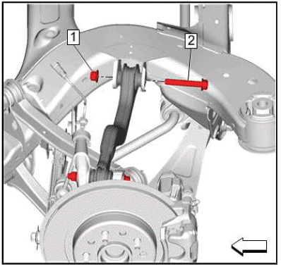
Rear Suspension Upper Control Arm Inner Nut(1) - Remove.
4. Rear Suspension Upper Control Arm Inner Bolt(2) - Remove and DISCARD.
5.
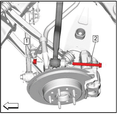
Rear Suspension Upper Control Arm Outer Nut(1) - Remove.
6. Rear Suspension Upper Control Arm Outer Bolt(2) - Remove and DISCARD.
7.
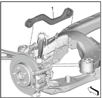
Rear Suspension Upper Lateral Link(1) - Remove.
Installation Procedure
1.
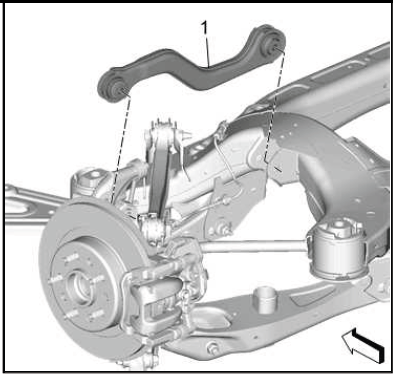
Rear Suspension Upper Lateral Link(1) - Install.
2.
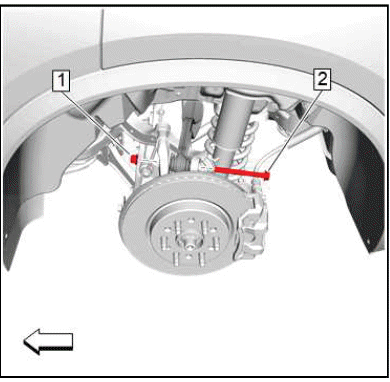
CAUTION: This vehicle is equipped with torque-to-yield or single use fasteners. Install a NEW torque-to-yield or single use fastener when installing this component.
Failure to replace the torque-to-yield or single use fastener could cause damage to the vehicle or component.
Rear Suspension Upper Control Arm Outer Bolt(2) - Install NEW.
CAUTION: Refer to Fastener Caution.
3. Rear Suspension Upper Control Arm Outer Nut(1) - Install and tighten.
- First Pass: 100 N.m (74 lb ft)
- Final Pass: (90 - 105 degrees)
4.
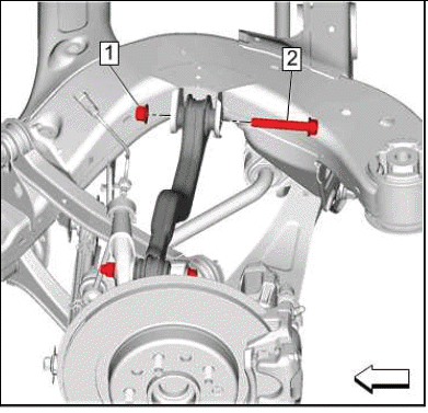
Rear Suspension Upper Control Arm Inner Bolt(2) - Install NEW.
5. Rear Suspension Upper Control Arm Inner Nut(1) - Install and hand tighten.
6. Rear Suspension Upper Control Arm Inner Bolt(2) - Tighten.
- First Pass: 100 N.m (74 lb ft)
- Final Pass: (90 - 105 degrees)
7. Raise the rear suspension cradle to its original position.
8. Remove the support and lower the vehicle.
REAR SUSPENSION UPPER TRAILING LINK REPLACEMENT
Removal Procedure
1. Raise and support the vehicle.
2. Lower the rear suspension cradle.
3.
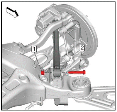
Rear Suspension Trailing Arm Nut(1) - Remove.
4. Rear Suspension Trailing Arm Bolt(2) - Remove and DISCARD.
5.
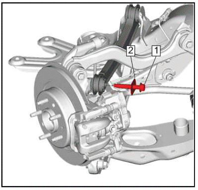
Rear Suspension Trailing Arm Bracket Bolt(1) - Remove and DISCARD.
6. Rear Suspension Trailing Arm Washer(2) - Remove.
7.
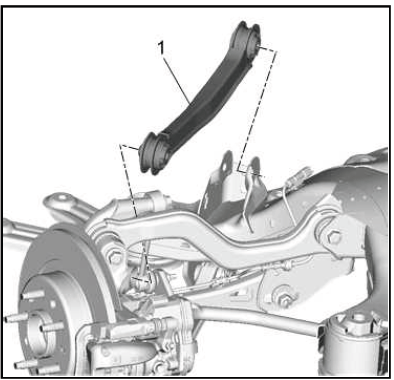
Rear Suspension Upper Trailing Link(1) - Remove.
Installation Procedure
1.
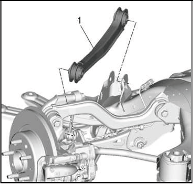
Rear Suspension Upper Trailing Link(1) - Install.
2.
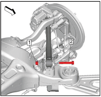
CAUTION: This vehicle is equipped with torque-to-yield or single use fasteners. Install a NEW torque-to-yield or single use fastener when installing this component.
Failure to replace the torque-to-yield or single use fastener could cause damage to the vehicle or component.
Rear Suspension Trailing Arm Bolt(2) - Install NEW.
3. Rear Suspension Trailing Arm Nut(1) - Install and hand tighten.
CAUTION: Refer to Fastener Caution.
4. Rear Suspension Trailing Arm Bolt(2) - Tighten.
- First Pass: 100 N.m (74 lb ft)
- Final Pass: (90 - 105 degrees)
5.
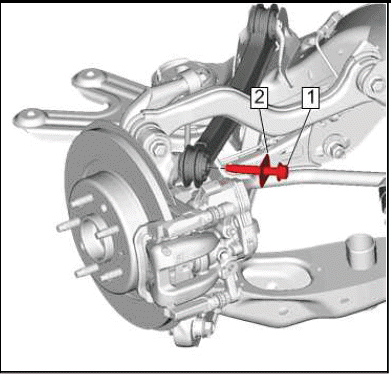
Rear Suspension Trailing Arm Washer(2) - Install.
6. Rear Suspension Trailing Arm Bracket Bolt(1) - Install NEW and tighten.
- First Pass: 100 N.m (74 lb ft)
- Final Pass: (90 - 105 degrees)
7. Raise the rear suspension cradle to its original position.
8. Remove the support and lower the vehicle.

