Buick Regal: Transmission Identification Information
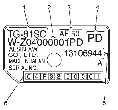
For automatic transmission AF50, the identification plate is on the top of the transmission housing.
- Aisin Warner transmission type
- Fabrication line 1 = 000001 - 500000 Fabrication line 2 = 500001 - 999999
- Transmission type (AF50)
- Model code
- GM parts number
- Production serial number
16 = Year of production (2016)
F = Month of production
- A: January
- B: February
- C: March
- D: April
- E: May
- F: June
- G: July
- H: August
- J: September
- K: October
- L: November
- M: December
38 = Model Designation
00001 = Production Serial Number
TRANSMISSION GENERAL DESCRIPTION
The AF50-8 is a compact, lightweight, next-generation electronically controlled 8-speed automatic transaxle that employs a ravigneaux-type planetary gear. It employs a high-precision clutch hydraulic control system for smooth, highly responsive gear shift feel.
Automatic Transaxle Features
Lock-up Control, Slip Control
Based on output rpm signals (NOUT), signals from the engine control unit (engine rpm and throttle opening) and vehicle speed, smooth lock up control is performed. Also, the slip rate is detected by adding input rpm signals (NIN), and slip control is performed.
Self Learning Control
The TCM helps provide smooth clutch engagement at gear shifting and smooth and delicate shifting while driving by performing shift control learning and garage shift control learning.
Neutral Control (N Control)
When the vehicle is at low speed or stopped in position "D", the transmission enters a neutral condition by releasing the clutch. By reducing drag loss of the torque converter, the load on the engine is lightened, fuel economy is enhanced, and idling vibration is reduced.
Manual Shift Control
By moving the shift lever from the "D" position into the manual shift position and shifting into + (upshift) or - (downshift), the driver can select the desired gear, enabling sporty driving that feels like a manual transmission.
A non-contact type shift position sensor has been adopted in the TCM. The sensor detects shift position by using the Hall Effect, which outputs specified voltage according to the shift position (P, R, N, D). The magnet position in the sensor changes when moving the shift lever, enabling the Hall IC to convert magnetic field strength into an electrical signal according to the shift position. Compared to the conventional contact type switch, the non-contact type sensor does not have contact points and is very compact. This makes it possible to integrate it with the TCM, improving reliability and durability.
If magnetic flux is applied perpendicularly to electric current flowing into a conductor or semiconductor, a potential difference, called Hall voltage, is generated perpendicularly in both the electric current and magnetic flux. This phenomenon is called the "Hall Effect".
A Hall IC is an electronic part that uses impetus caused by potential difference when a magnetic field is generated.
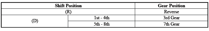
With the fail-safe function, if any malfunction should occur in the automatic transmission system, the TCM will output a control signal, and control will be performed to make traveling a minimum distance possible. If a shift solenoid malfunctions, the TCM will cancel the output of control signals to the solenoid. If this happens, oil pressure circuits alone will control automatic transmission gear shifting. The gears will shift as shown in the chart below.
The transmission may be operated in any of the following gear ranges:
PARK (P)
This position locks the front wheels and prevents the vehicle from rolling either forward or backward. PARK is the best position to use when starting the vehicle. Because the transmission utilizes a shift lock control system, it is necessary to fully depress the brake pedal before shifting out of PARK. For safety reasons, use the parking brake in addition to the PARK position.
REVERSE (R)
This position allows the vehicle to be operated in a rearward direction.
NEUTRAL (N)
This position allows the engine to be started and operated while driving the vehicle. If necessary, you may select this position in order to restart the engine with the vehicle moving. This position should also be used when towing the vehicle.
DRIVE (D)
Drive range should be used for all normal driving conditions for maximum efficiency and fuel economy. Drive range allows the transmission to operate in each of the 8 forward gear ratios. Downshifts to a lower gear, or higher gear ratio, are available for safe passing by depressing the accelerator or by manually selecting a lower gear in the manual mode range.
TRANSMISSION ADAPTIVE FUNCTIONS
The transmission control module (TCM) utilizes speed sensor data during commanded shifts to determine if a shift is occurring too fast (harsh) or too slow (soft). Transmission build variation and normal wear of the clutches can cause the shift time (the time required to apply a clutch) to be longer or shorter than desired. In order to compensate for these changes, the transmission control module (TCM) adjusts the current output to the various pressure control solenoid valves, to maintain the originally calibrated shift timing. This self-learning process is referred to as "adaptive learning" which is used to ensure consistent shift feel and increase transmission durability.
READ NEXT:
 Electronic Component Description
Control Module
K71 Transmission Control Module
The TCM (2) is mounted directly on top of the transmission (1). The selector
lever and transmission range sensor is
integrated in the control module. T
Special Tools and Equipment
SPECIAL TOOLS
DT-26941
J-26941
Remover
DT-37228
J-37228
Seal Cutter
DT-43911
J-43911
Selector Shaft Seal
Remover
DT-44215
J-44215
Rear Seal Installer
DT-44809
J-44809
Output Shaft Seal
Installer
SEE MORE:
Auxiliary Water Pump Replacement (FWD)
Removal Procedure
1. Drain the cooling system.
2.
Steering Gear Heat Shield (2) - Remove.
3.
Heater Outlet Hose Clamp (1) - Disengage.
4. Heater Outlet Hose (2) @ Auxiliary Water Pump - Remove.
5.
Heater Coolant Pump Hose Clamp (1) - Disengage.
6. Heater Coolant Pump Hose (2) @ Auxiliary Wa
Component Cleaning
* PLEASE READ THIS FIRST *
NOTE: Examples used in this article are general in nature and do not
necessarily
relate to a specific engine or system. Illustrations and procedures have
been chosen to guide mechanic through engine overhaul process.
Descriptions of processes of cleaning, inspection, ass
