Buick Regal: Crankshaft Balancer Cleaning and Inspection
.png)
1. Crankshaft Balancer
WARNING: Refer to Safety Glasses Warning.
Procedure
- Clean the crankshaft balancer.
- Clean the belt grooves of all dirt or debris with a wire brush.
- Dry the crankshaft balancer with compressed air.
- Inspect the crankshaft balancer for the following:
Worn, grooved, or damaged hub seal surface - a crankshaft balancer hub seal
surface with excessive scoring, grooves, rust or other damage must be
replaced.
Dirty or damaged belt grooves - The balancer belt grooves should be free of any nicks, gouges, or other damage that may not allow the belt to track properly.
Worn, chunking or deteriorated rubber between the hub and pulley.
Minor imperfections may be removed with a fine file.
AUTOMATIC TRANSMISSION FLEX PLATE CLEANING AND INSPECTION
1.
.png)
Clean the flywheel (2) in solvent.
WARNING: Refer to Safety Glasses Warning.
2. Dry the flywheel with compressed air.
3. Inspect the flywheel for the following:
- Damaged ring gear teeth.
- Stress cracks around the flywheel-to-crankshaft bolt hole locations.
- Weight saving holes.
CRANKSHAFT AND BEARING CLEANING AND INSPECTION
Special Tools
GE-7872 Magnetic Base Dial Indicator Set
For equivalent regional tools, refer to Special Tools.
1.
.png)
NOTE: Use care when handling the crankshaft. Avoid damage to the bearing surfaces or the lobes of the crankshaft position reluctor ring. Damage to the teeth of the crankshaft position reluctor ring may affect on-board diagnostic (OBD) II system performance.
Clean the crankshaft (1) with solvent.
2. Thoroughly clean all oil passages and inspect for restrictions or burrs.
WARNING: Refer to Safety Glasses Warning.
3. Dry the crankshaft with compressed air.
NOTE: Reluctor ring teeth should not have imperfections on the rising or falling edges.
Imperfections of the reluctor ring teeth may effect OBD II system performance.
4. Perform a visual inspection of the crankshaft for damage.
5. Inspect the crankshaft reluctor ring. Replace the crankshaft assembly if damage to the reluctor ring is present.
6. Inspect the crankshaft journals for wear. The journals should be smooth, with no signs of scoring, wear, or damage.
7. Inspect the crankshaft journals for grooves or scoring.
8. Inspect the crankshaft journals for scratches or wear.
9. Inspect the crankshaft journals for pitting or imbedded bearing material.
10. Measure the crankshaft journals for out-of-round.
11. Measure the crankshaft journals for taper.
12.
.png)
Measure the crankshaft runout.
Using wooden V-blocks, support the crankshaft on the front and rear journals.
13. Use the GE-7872 indicator (1) in order to measure the crankshaft runout at the front and rear intermediate journals.
14. Use the GE-7872 indicator in order to measure the runout of the crankshaft rear flange.
15. Replace the crankshaft if the measurements are not within specifications.
16.
.png)
NOTE: Crankshaft bearings MUST be separated, marked, or organized in a way to ensure installation to their original location and position, when suitable for use.
Inspect crankshaft bearings for craters or pockets (1). Flattened sections on the bearing halves also indicate fatigue.
17. Inspect the crankshaft bearings for excessive scoring or discoloration (2).
18. Inspect the crankshaft bearings for dirt or debris imbedded into the bearing material.
19. Inspect the crankshaft bearings for improper seating indicated by bright, polished sections of the bearing (3).
If the lower half of the bearing is worn or damaged, both upper and lower halves should be replaced.
Generally, if the lower half is suitable for use, the upper half should also be suitable for use.
PISTON AND CONNECTING ROD DISASSEMBLE
Special Tools
- EN-46745 Piston Pin Clip Remover/Installer
- EN-46745-4 Piston Pin Clip Remover/Installer Adapter
For equivalent regional tools, refer to Special Tools.
1.
.png)
WARNING: Handle the piston carefully. Worn piston rings are sharp and may cause bodily injury.
Disassemble the piston rings (1, 2, 3, 4, 5). Use a suitable tool to expand the rings. The piston rings must not be reused.
2.
.png)
NOTE: Two retainers hold each piston pin in place. Ensure that the piston pin is not damaged. Do not reuse the retainers.
NOTE: Use the appropriate adapter for EN-46745 remover to remove the retainers.
The appropriate adapter will fit the piston pin ID and allow the ring to be removed or installed.
- For LCV/LKW/LD4 piston pin, use EN-46745-2 adapter.
- For LTG piston pin, use EN-46745-4 adapter.
Remove the piston pin retainers using the EN-46745 remover (1) and the appropriate adapter. Discard the retainer.
3.
.png)
Remove the piston pin (1) and the connecting rod (3) from the piston (2).
PISTON, CONNECTING ROD, AND BEARING CLEANING AND INSPECTION
Connecting Rod Measurement
1.
.png)
Clean the connecting rods (1) in solvent and dry with compressed air.
2. Inspect the connecting rods for the following:
- Signs of being twisted, bent, nicked, or cracked
- Scratches or abrasion on the rod bearing seating surface
3. If the connecting rod bores contain minor scratches or abrasions, clean the bores in a circular direction with a light emery paper. DO NOT scrape the rod or rod cap.
4. If the beam of the rod is scratched or has other damage replace the connecting rod.
5. Measure the piston pin to connecting rod bore using the following procedure:
- Using an outside micrometer, take two measurements of the piston pin in the area of the connecting rod contact.
- Using an inside micrometer, measure the connecting rod piston pin bore.
- Subtract the piston pin diameter from the piston pin bore diameter.
- The clearance should not be more than 0.021 mm (0.0008 in).
6. If there is excessive clearance, replace the piston pin.
7. If there is still excessive clearance, replace the connecting rod.
Piston Measurement
1.
Clean the piston skirts and the pins with a cleaning solvent. DO NOT wire brush any part of the piston.
2. Clean the piston ring grooves with a groove cleaner. Make sure oil ring holes and slots are clean.
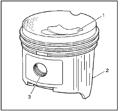
3. Inspect the pistons for the following conditions:
- Cracked ring lands, skirts, or pin bosses
- Ring grooves for nicks, burrs that may cause binding
- Warped or worn ring lands
- Eroded areas at the top of the piston (1)
- Scuffed or damaged skirts (2)
- Worn piston pin bores (3)
4. Replace pistons that show any signs or damage or excessive wear.
5. Measure the piston pin bore to piston pin clearances using the following procedure:
- Piston pin bores and pins must be free of varnish or scuffing.
- Use an outside micrometer to measure the piston pin in the piston contact areas.
- Using an inside micrometer, measure the piston pin bore.
- Subtract the measurement of the piston pin bore from the piston pin. The clearance should be within 0.002 - 0.012 mm (0.00007 - 0.00047 in).
- If the clearance is excessive, determine which component is out of specification.
6.
.png)
Measure the piston ring end gap using the following procedure:
- Place the piston ring in the area of the bore where the piston ring will travel (approximately 25 mm or 1 inch down from the deck surface). Be sure the ring is square with the cylinder bore by positioning the ring with the piston head.
- Measure the end gap of the piston ring with feeler gauges (1). Compare
the measurements with those
provided below:
- The top compression ring end gap should be 0.20 - 0.40 mm (0.0060 - 0.015 in).
- The second compression ring end gap should be 0.35 - 0.55 mm (0.0137 - 0.0216 in).
- The oil ring end gap should be 0.25 - 0.76 mm (0.0098 - 0.029 in).
- If the clearance exceeds the provided specifications, the piston rings must be replaced.
- Repeat the procedure for all the piston rings.
7.
.png)
Measure the piston ring side clearance using the following procedure:
- Roll the piston ring entirely around the piston ring groove. If any binding is caused by a distorted piston ring, replace the ring.
- With the piston ring on the piston, use feeler gauges (1) to check clearance at multiple locations.
- The clearance between the surface of the top piston ring and the ring land should be no greater than 0.075 mm (0.0030 in).
- If the clearance is greater than specifications, replace the piston ring.
- If the new ring does not reduce the top ring side clearance to 0.075 mm (0.0030 in) or less, install a new piston.
8. The top compression ring may be installed with either side up. There is a locating dimple on the 2nd compression ring near the end for identification of the top side. Install the 2nd compression ring with the dimple facing up.
9. The clearance between the surface of the second piston ring and the ring land should be no greater than 0.069 mm (0.0026 in).
10. If the new ring does not reduce the clearance to 0.069 mm (0.0026 in) or less, install a new piston.
11.
.png)
Measure piston width using the following procedure:
- Using an outside micrometer (2), measure the width of the piston 14.5 mm (0.570 in) above the bottom of the piston skirt at the thrust surface perpendicular to the centerline of the piston pin.
- Compare the measurement of the piston to its original cylinder by subtracting the piston width from the cylinder diameter.
- The proper clearance specification for the piston is 0.010 - 0.041 mm (0.0004 - 0.0016 in).
12. If the clearance obtained through measurement is greater than these specifications and the cylinder bores are within specification, replace the piston (1).
Piston Selection
1.
.png)
NOTE: Measurements of all components should be taken with the components at normal room temperature.
For proper piston fit, the engine block cylinder bores must not have excessive wear or taper.
A used piston and pin set may be reinstalled if, after cleaning and inspection, they are within specifications.
Inspect the engine block cylinder bore. Refer to Engine Block Cleaning and Inspection.
2. Inspect the piston and the piston pin.
3. Use a bore gauge (1) and measure the cylinder bore diameter. Measure at a point 64 mm (2.5 in) from the top of the cylinder bore.
4.
.png)
Measure the bore gauge with a micrometer (1) and record the reading.
5.
.png)
With a micrometer (2) or caliper at a right angle to the piston (1), measure the piston 14 mm (0.570 in) from the bottom of the skirt.
6. Subtract the piston diameter from the cylinder bore diameter in order to determine piston-to-bore clearance.
7. For proper piston-to-bore clearance. Refer to Engine Mechanical Specifications.
8. If the proper clearance cannot be obtained, select another piston and measure for the clearances.
9. If the proper fit cannot be obtained, hone the cylinder bore or replace the cylinder block.
10. When the piston-to-cylinder bore clearance is within specifications, mark the top of the piston using a permanent marker for installation to the proper cylinder. Refer to Separating Parts.
READ NEXT:
 Piston and Connecting Rod Assemble
Special Tools
EN-46745 Piston Pin Clip Remover/Installer
EN-46745-4 Piston Pin Clip Remover/Installer Adapter
For equivalent regional tools, refer to Special Tools.
1.
NOTE: Install the piston on
Cylinder Head Disassemble
Special Tools
EN-43963 Valve Spring Compressor (off car)
EN-46116 Valve Stem Seal Remover/Installer
EN-50717 Valve Spring Compressor
For equivalent regional tools, refer to Special Tools.
1.
Rem
Valve and Seat Grinding
Valve Measurement and Reconditioning Overview
Proper valve service is critical to engine performance. Therefore, all
detailed measurement procedures must be
followed to identify components that a
SEE MORE:
Cruise Control
With cruise control the vehicle can
maintain a speed of about 40 km/h
(25 mph) or more without keeping
your foot on the accelerator. Cruise
control does not work at speeds
below 40 km/h (25 mph).
Warning:
Cruise control can be dangerous
where you cannot drive safely at
a steady speed. Do not use
cru
DTC C1587
Diagnostic Instructions
Perform the Diagnostic System Check - Vehicle prior to using this
diagnostic procedure.
Review Strategy Based Diagnosis for an overview of the diagnostic
approach.
Diagnostic Procedure Instructions provide an overview of each diagnostic
category.
DTC Descriptors
DT
