Buick Regal: Cylinder Head Replacement
Removal Procedure
Special Tools
- EN-38188 Cylinder Head Broken Bolt Extractor Kit - or equivalent aftermarket tool
- EN-45059 Angle Meter
- EN-36857 Engine Lift Bracket
Equivalent regional tools: Special Tools
1. Cooling System Draining and Filling (Static) Cooling System Draining and Filling (GE 47716) - Drain.
2. Camshaft Cover Replacement - Remove.
3. Fuel Pump Replacement - Remove.
4. Intake Manifold Replacement - Remove.
5. Exhaust Manifold Replacement - Remove.
6. Engine Front Cover Replacement - Remove.
7. Camshaft Position Actuator and Camshaft Replacement - Intake - Remove.
8. Camshaft Position Actuator and Camshaft Replacement - Exhaust - Remove.
9.
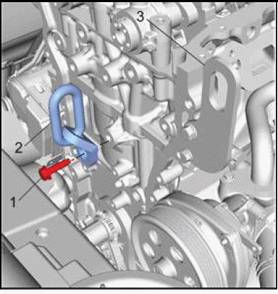
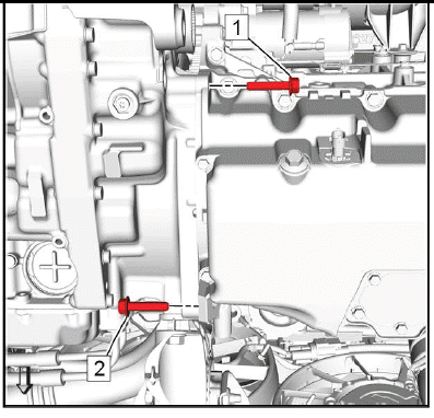
Install the EN-36857 Engine Lift Bracket (2) and fastener (1) into the engine block.
NOTE: Support the engine as necessary from underneath while repositioning the engine support fixture.
10. Reposition the engine support fixture lift hook from the engine lift bracket (3) to the EN-36857 Engine Lift Bracket (2) 11.
Cylinder Head Bolt - Remove and DISCARD.
12.
CAUTION: In order to prevent damage to the valves and injectors during cylinder head removal, set the cylinder head on blocks.
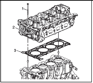
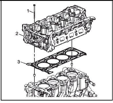
Cylinder Head Bolt (1) - Remove and DISCARD [10x].
13. Cylinder Head (2) - Remove.
14. Cylinder Head Gasket (3) - Remove and DISCARD.
15. Replace or transfer locating pins as necessary.
16. Use the following procedures when cleaning the cylinder head and cylinder block surfaces:
- Be careful not to gouge or scratch the gasket surfaces. Do not gouge or scrape the combustion chamber surfaces. The feel of the gasket surface is important, not the appearance. There will be indentations from the gasket left in the cylinder head after all of the gasket material is removed. These small indentations will be filled in by the new gasket.
- Use a gasket scraper to clean the cylinder head and cylinder block gasket surfaces. Do not scratch or gouge any surface.
- Do not use any other method or technique to clean these gasket surfaces.
NOTE: Do not use a tap to clean the cylinder head bolt holes.
17. Clean the old sealer/lube and dirt from the bolt holes.
18. Clean the bolt holes with a nylon bristle brush.
WARNING: Wear safety glasses to avoid injury when using compressed air or any cleaning solvent. Bodily injury may occur if fumes are inhaled or if skin is exposed to chemicals.
19. When cleaning the cylinder head bolt holes use a suitable commercial spray liquid solvent and compressed air from an extended-tip blow gun to reach the bottom of the holes.
20. Remove any broken long cylinder head bolts using the EN 38188 kit.
21. If replacing the cylinder head, transfer all parts as necessary.
22. Cylinder Head - Clean and inspect.
Installation Procedure
1. If replacing the cylinder head, transfer all parts as necessary.
2.
NOTE: Do not use any sealing material.
NOTE: Install a NEW gasket.
Cylinder Head Gasket (3) - Install.
3. Ensure the number 1 cylinder is at top dead center (TDC). The key on the crankshaft should be on top in the 12 o'clock position.
4. Cylinder Head (2) - Install.
5. Install NEW bolts.
Cylinder Head Bolt (1) - Loosely install [10x].
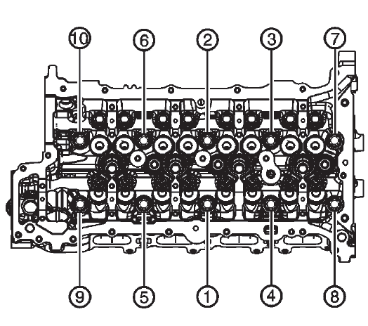
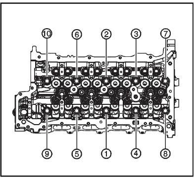
Fig. 8: Cylinder Head Bolts Tightening Sequence
6.
Tighten in the sequence shown.
Tighten
- First Pass: tighten the bolts in sequence to 30 N.m (22 lb ft).
- Final Pass: tighten the bolts an additional 190 degrees in sequence using the EN 45059 meter.
7.
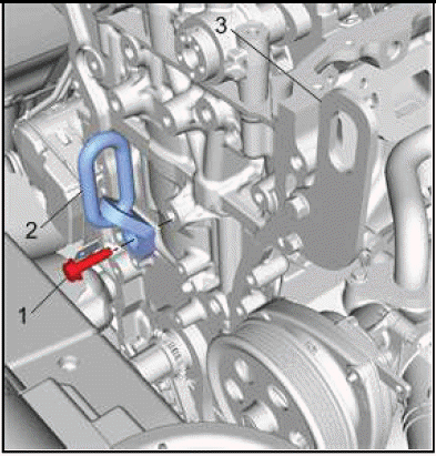
Support engine as necessary from underneath to allow repositioning the engine support lift fixture hook to the EN-36857 Engine Lift Bracket (2). Engine Support Fixture.
8. Reposition the engine support fixture lift hook from the EN-36857 Engine Lift Bracket (2) to the engine lift bracket (3).
9. Remove the EN-36857 Engine Lift Bracket (2) and fastener (1) from the engine block.
10. Camshaft Position Actuator and Camshaft Replacement - Intake - Install.
11. Camshaft Position Actuator and Camshaft Replacement - Exhaust - Install.
12. Engine Front Cover Replacement - Install.
13. Exhaust Manifold Replacement - Install.
14. Intake Manifold Replacement - Install.
15. Fuel Pump Replacement - Install.
16. Camshaft Cover Replacement - Install.
17. Change the engine oil and filter.
18. Cooling System Draining and Filling (Static) Cooling System Draining and Filling (GE 47716) - Fill.
OIL PAN REPLACEMENT
Removal Procedure
1. Support the engine.
2. Drain the engine oil.
3. Remove the engine front cover.
4. Exhaust Front Pipe - Remove.
5. Remove the catalytic converter. Warm Up Three-Way Catalytic Converter. Replacement (2.0L LTG).
6. Remove the engine oil cooler.
7. Front Compartment Air Deflector - Right Side - Remove.
8. Power Transfer Unit Case - Remove.
9.
.png)
Air Conditioning Compressor Bolt (1) - Remove.
10.
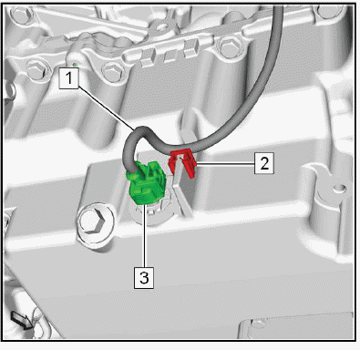
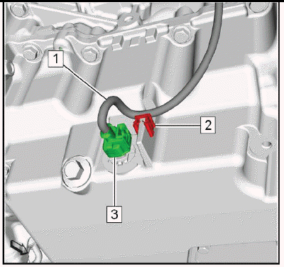
Wiring Harness Retainer (2) - Remove.
11. Disconnect the electrical connector. (3)
12. Wiring Harness (1) - Position aside.
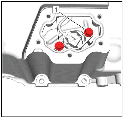
13.
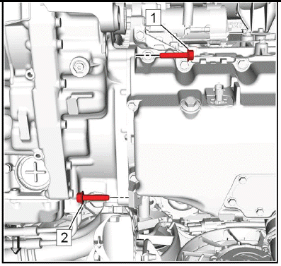
Transmission Bolt (1, 2) - Remove [2x].
14.
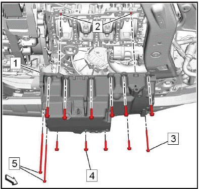
NOTE: Take note that there are different bolt lengths.
Oil Pan Bolt (3, 4, 5) - Remove [13x].
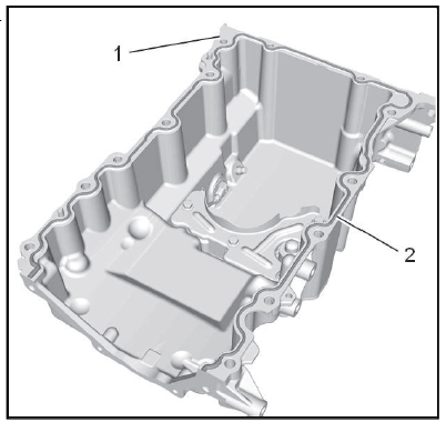
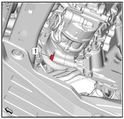
15. Remove the oil pan. (1)
16. Ensure that the location pins (2) are in the lower crankcase.
Disassemble Procedure
1. Engine Oil Level Indicator Switch - Remove.
Assemble Procedure
1. Engine Oil Level Indicator Switch - Install.
2. Clean the sealing surface of the engine block and the engine front cover from old gasket material, oil, dirt and grease.
Installation Procedure
1.
NOTE:
- The lower crankcase surface must be free of contamination prior to applying the sealer.
- Install and align the oil pan to block within 10 minutes of applying the sealer.
- The oil pan must be fastened to final torque specification within 60 minutes of applying the sealer.
Clean the sealing surface of the lower crankcase and the engine front cover from old gasket material, oil, dirt and grease.
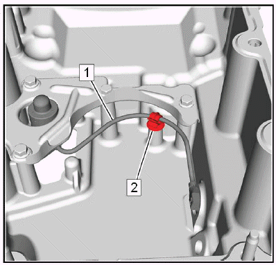
2. In case of reusing the old oil pan, clean and inspect the oil pan.
3. Apply a 4.25 mm (0.167 in) bead of sealer (2) on the level part of the flange around the perimeter of the oil pan (1) as shown.
4.
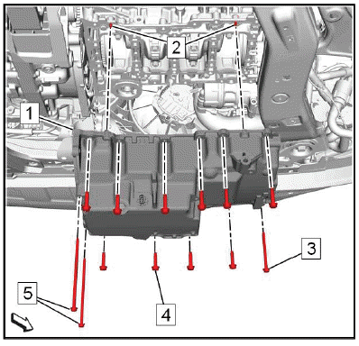
NOTE: When installing the oil pan, carefully align the oil pan (1) to the locating pins (2) then install the pan onto the lower crankcase.
Install the oil pan. (1)
CAUTION: Fastener Caution.
5. Oil Pan Bolt (3, 4, 5) - Install and hand tighten [13x].
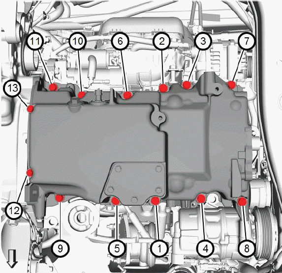
Fig. 9: Engine Oil Pan Bolts Tightening Sequence
6.
Oil Pan Bolt - Tighten in sequence
- Tighten bolts in sequence 1 - 11 to 25N.m (18 lb ft).
- Tighten bolts in sequence 12 - 13 to 10N.m (89 lb in).
7.
Transmission Bolt (1, 2) - Install and tighten [2x]58N.m (43 lb ft).
8.
Air Conditioning Compressor Bolt (1) - Install and tighten22N.m (16 lb ft).
9.
Connect the electrical connector. (3)
10. Wiring Harness Retainer (2) - Install.
11. Power Transfer Unit Case - Install.
12. Front Compartment Air Deflector - Right Side - Install.
13. Install the engine oil cooler.
14. Install the catalytic converter. Warm Up Three-Way Catalytic Converter Replacement (2.0L LTG).
15. Exhaust Front Pipe - Install - Exhaust Front Pipe Replacement (LTG).
16. Install the engine front cover.
17. Check and correct the engine oil level.
18. Engine Support Fixture - Remove.
ENGINE OIL LEVEL INDICATOR SWITCH REPLACEMENT
Removal Procedure
1. Remove the oil pan.
CAUTION: Ensure care is taken NOT to damage the mating surfaces of the oil pan and of the case or oil leaks may occur.
2. Place the oil pan onto a workbench.
3. Lay a lint-free cloth under the oil pan.
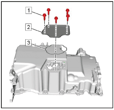
4.
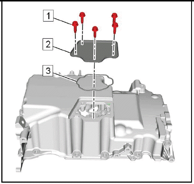
Oil Pan Cover Bolt (1) - Remove [5x].
5. Oil Pan Cover (2) - Remove.
6. Remove and DISCARD the seal. (3)
7.
Engine Oil Level Indicator Switch Bolt (1) - Remove [2x].
8.
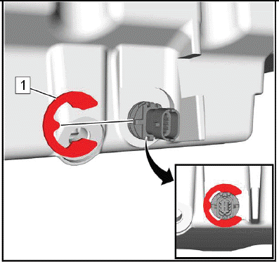
Engine Oil Level Indicator Switch Connector Retainer (1) - Remove.
9.
Wiring Harness (1) @ Wiring Harness Clip (2) - Unclip.
10.
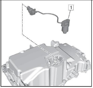
Engine Oil Level Indicator Switch (1) - Remove.
Installation Procedure
1.
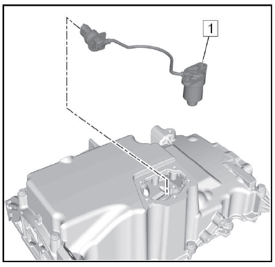
Engine Oil Level Indicator Switch (1) - Install.
2.
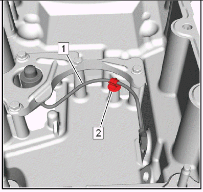
Wiring Harness (1) @ Wiring Harness Clip (2) - Install.
3.
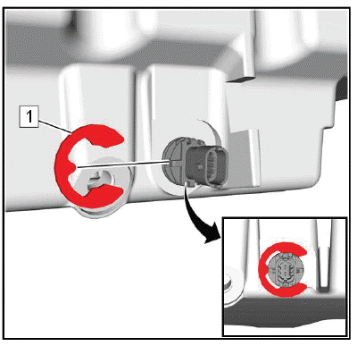
NOTE: Ensure the correct position of the engine oil level indicator switch connector retainer (1).
Engine Oil Level Indicator Switch Connector Retainer (1) - Install.
4.
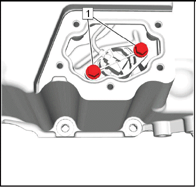
CAUTION: Fastener Caution.
Engine Oil Level Indicator Switch Bolt (1) - Install and tighten [2x]10N.m (89 lb in).
5.
Install a NEW seal. (3)
6. Oil Pan Cover (2) - Install.
7. Oil Pan Cover Bolt (1) - Install and tighten [5x]10N.m (89 lb in).
8. Install the oil pan. Oil Pan Replacement.
READ NEXT:
 Automatic Transmission Flex Plate Replacement
Special Tools
EN-45059 Angle Meter
EN-50792 Holding Tool
Equivalent regional tools: Special Tools
Removal Procedure
1. Remove the transmission.
2.
To prevent crankshaft rotation, install the EN
Engine Replacement
Removal Procedure
1. Upper Intermediate Steering Shaft - Remove.
2. Recover the refrigerant. Refrigerant Recovery and Recharging (R-1234yf).
3. Drain the coolant. Cooling System Draining and Filling
Engine Oil and Oil Filter Replacement
Removal Procedure
1. Raise and support the vehicle.
2. Place a drain pan under the vehicle.
3.
Oil Pan Drain Plug (1) - Remove.
4. Oil Pan Drain Plug Seal (2) - Remove and DISCARD.
5. Drain the e
SEE MORE:
General Information
Your vehicle is an important
investment. This section describes
the required maintenance for the
vehicle. Follow this schedule to help
protect against major repair
expenses resulting from neglect or
inadequate maintenance. It may
also help to maintain the value of
the vehicle if it is sold. It is th
Head Restraints
If equipped with base seats, the
vehicle's front seats have adjustable
head restraints in the outboard
seating positions.
If equipped with GS Model seats,
the vehicle's front seats have head
restraints in the outboard seating
positions that cannot be adjusted.
Warning:
With head restraints that are
