Buick Regal: Cylinder Leakage Test
Special Tools
EN 35667-A Cylinder Head Leakdown Tester
For equivalent regional tools, refer to Special Tools.
NOTE: A leakage test may be performed in order to measure cylinder/combustion chamber leakage. High leakage may indicate one or more of the following:
- Worn or burnt valves
- Broken valve springs
- Stuck valve lash adjusters
- Incorrect valve lash/adjustment
- Damaged piston
- Worn piston rings
- Worn or scored cylinder bore
- Damaged cylinder head gasket
- Cracked or damaged cylinder head
- Cracked or damaged engine block
WARNING: Unless directed otherwise, the ignition must be OFF with the key removed, and all electrical loads must be OFF before servicing any electrical component. Disconnect the negative battery cable to prevent an electrical spark should a tool or equipment come in contact with an exposed electrical terminal. Failure to follow these precautions may result in personal injury and/or damage to the vehicle or its components.
For Vehicles equipped with OnStar (UE1) with Back Up Battery: The Back Up Battery is a redundant power supply to allow limited OnStar functionality in the event of a main vehicle battery power disruption to the VCIM (OnStar module). Do not disconnect the main vehicle battery or remove the OnStar fuse with the ignition key in any position other than OFF. Retained accessory power should be allowed to time out or be disabled (simply opening the driver door should disable retained accessory power) before disconnecting power. Disconnecting power to the OnStar module in any way while the ignition is On or with retained accessory power activated may cause activation of the OnStar Back-Up Battery system and will discharge and permanently damage the back-up battery. Once the Back-Up Battery is activated it will stay on until it has completely discharged. The backup battery is not rechargeable and once activated the back-up battery must be replaced.
1. Disconnect the battery ground negative cable.
2. Remove the spark plugs. Refer to Spark Plug Replacement in Engine Controls.
3. Rotate the crankshaft to place the piston in the cylinder being tested at Top Dead Center (TDC) of the compression stroke.
4. Install the EN 35667-A tester or equivalent.
NOTE: It may be necessary to hold the crankshaft balancer bolt to prevent the engine from rotating.
5. Apply shop air pressure to the EN 35667-A tester and adjust according to the manufacturers instructions.
6. Record the cylinder leakage value. Cylinder leakage that exceeds 25 percent is considered excessive and may require component service. In excessive leakage situations, inspect for the following conditions:
- Air leakage sounds at the throttle body or air inlet hose that may indicate a worn or burnt intake valve or a broken valve spring.
- Air leakage sounds at the exhaust system tailpipe that may indicate a worn or burnt exhaust valve or a broken valve spring.
- Air leakage sounds from the crankcase, oil level indicator tube, or oil fill tube that may indicate worn piston rings, a damaged piston, a worn or scored cylinder bore, a damaged engine block or a damaged cylinder head.
- Air bubbles in the cooling system may indicate a damaged cylinder head or a damaged cylinder head gasket.
7. Perform the leakage test on the remaining cylinders and record the values.
OIL CONSUMPTION DIAGNOSIS
Excessive oil consumption, not due to leaks, is the use of 0.9 L (1 qt) or greater of engine oil within 3 200 kilometers (2, 000 miles). The causes of excessive oil consumption include the following conditions:
- External oil leaks
Tighten bolts and/or replace gaskets and oil seals as necessary. - Incorrect oil level or improper reading of oil level indicator
With the vehicle on a level surface, allow adequate drain down time and inspect for the correct oil level. - Improper oil viscosity
Use recommended SAE viscosity for the prevailing temperatures. - Continuous high speed driving and/or severe usage
- Crankcase ventilation system restrictions or malfunctioning components
- Valve guides and/or valve stem oil seals worn, or the seal omitted
Ream guides and install oversize service valves and/or new valve stem oil seals. - Piston rings broken, improperly installed, worn, or not seated
properly
Allow adequate time for rings to seat. Replace broken or worn rings, as necessary. - Piston improperly installed or mis-fitted
OIL PRESSURE DIAGNOSIS AND TESTING
Special Tools
- EN-21867-850 Oil Pressure Gauge Adapter
- GE-21867-A Oil Pressure Gauge Kit
For equivalent regional tools, refer to Special Tools.
1. With the vehicle on a level surface, allow adequate drain down time of 2 - 3 minutes and measure for a low oil level.
Add the recommended grade engine oil and fill the crankcase until the oil level measures full on the oil level indicator.
2. Run the engine, and verify low, or no oil pressure on the vehicle gauge or light.
Listen for a noisy valve train or a knocking noise.
3. Inspect for the following:
- Correct oil filter with anti-drain back feature and O-ring on the cylinder block side of the filter
- Oil diluted by moisture or unburned fuel mixtures
- Improper oil viscosity for the expected temperature
- Incorrect or malfunctioning oil pressure sender
- Incorrect or malfunctioning oil pressure gauge
- Plugged oil filter
- Malfunctioning oil bypass valve
4. Remove the oil pressure sender or another engine block oil gallery plug.
5. Install EN-21867-850 adapter and GE-21867 gauge and measure the engine oil pressure.
6. Compare the readings to specifications. Refer to Engine Mechanical Specifications.
7. If the engine oil pressure is below specifications, inspect the engine for one or more of the following:
- Correct oil filter with anti-drain back feature and O-ring on the cylinder block side of the filter
- Oil pump worn or dirty
- Oil pump screen loose, plugged, or damaged
- Oil pump screen O-ring seal missing or damaged
- Malfunctioning oil control valve solenoid
- Excessive bearing clearance
- Cracked, porous or restricted oil galleries
- Oil gallery plugs missing or incorrectly installed
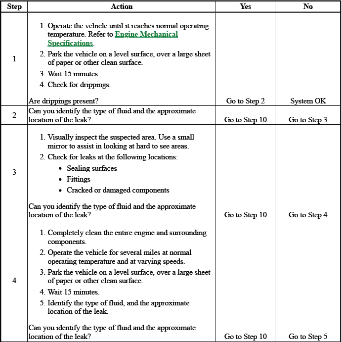
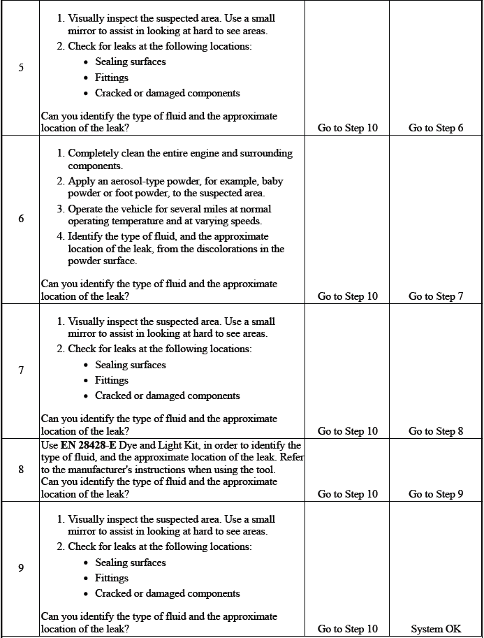
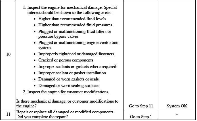
OIL LEAK DIAGNOSIS
DEFINITION: You can repair most fluid leaks by first, visually locating the leak, repairing or replacing the component, or by resealing the gasket surface. Once the leak is identified, determine the cause of the leak. Repair the cause of the leak as well as the leak itself.
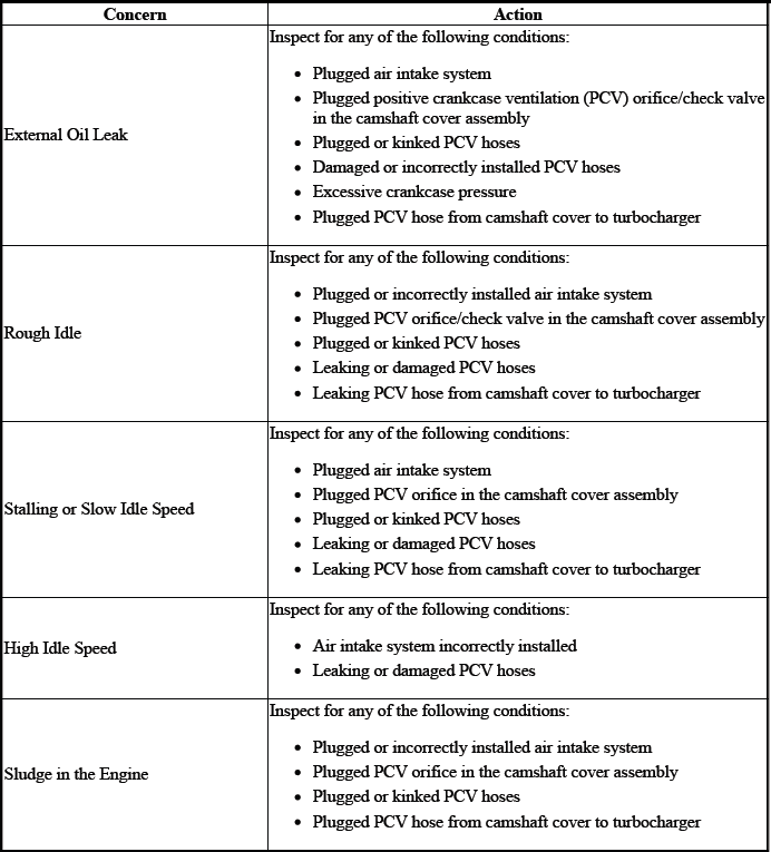
CRANKCASE VENTILATION SYSTEM INSPECTION/DIAGNOSIS
Special Tools
EN 23951 Valve Manometer
For equivalent regional tools, refer to Special Tools.
1. Verify clean air cleaner.
2. Verify oil fill cap is in place.
3. Verify oil level indicator is installed.
4. Remove the oil level indicator. Install a EN 23951 valve manometer or equivalent, into the oil level indicator hole.
5. Start the engine.
6. Check for slight vacuum. The vacuum level should be less than 3.377 kPa (13.571 in H2 O).
7. If vacuum is higher, inspect and verify that the clean air hose from cam cover to air intake is not blocked or kinked.
8. If vacuum is in the normal range, remove the PCV line from the fresh air valve near oil fill cap. Block fresh air valve and also plug the fresh air hose. Vacuum should increase on the manometer. If held too long, vacuum will be drawn through the crankshaft seals creating a sucking sound.
9. If vacuum does not increase, the orifice in the camshaft cover assembly could be plugged. The valve is between the camshaft cover assembly and the cylinder head assembly.
10. If there is zero vacuum or pressure, verify compression of the engine.
11. If compression is normal, check for a blocked orifice at the camshaft cover assembly. Clean the orifice.
12. The hose from valve cover to the turbo is also for the positive crankcase ventilation (PCV) and is used for PCV flow under normal operation and only PCV flow during turbo boost conditions. If the hose is plugged, replace the PCV hose assembly and PCV fitting assembly at the turbocharger.
READ NEXT:
 Drive Belt Chirping, Squeal, and Whine Diagnosis
Diagnostic Aids
A chirping or squeal noise may be intermittent due to moisture on the
drive belts or the pulleys. It may be
necessary to spray a small amount of water on the drive belts in order
Intake Manifold Cover Replacement
Engine Oil Filler Cap
Intake Manifold Cover Bolt [3x]
Tighten
9 N.m (80 lb in)
Intake Manifold Cover
DRIVE BELT REPLACEMENT
Fig. 1: Drive Belt Routing Diagram (2.0L)
Preliminary Procedure
SEE MORE:
Airbag Indicator Malfunction (Passenger)
Diagnostic Instructions
Perform the Diagnostic System Check - Vehicle prior to using this
diagnostic procedure.
Review Strategy Based Diagnosis for an overview of the diagnostic
approach.
Diagnostic Procedure Instructions provides an overview of each
diagnostic category.
Diagnostic Fault
DTC P0700
Diagnostic Instructions
Perform the Diagnostic System Check - Vehicle prior to using this
diagnostic procedure.
Review Strategy Based Diagnosis for an overview of the diagnostic
approach.
Diagnostic Procedure Instructions provides an overview of each of the
diagnostic category.
DTC Descri
