Buick Regal: DTC P0705, P0707, P0708, or P0851
Diagnostic Instructions
- Perform the Diagnostic System Check prior to using this diagnostic procedure: Refer to Diagnostic System Check - Vehicle
- Review the description of Strategy Based Diagnosis: Refer to Strategy Based Diagnosis
- An overview of each diagnostic category can be found here: Refer to Diagnostic Procedure Instructions
DTC Descriptor
NOTE: This procedure may also diagnose malfunctions that are not detected by a DTC.
DTC P0705
Transmission Range Switch Circuit
DTC P0707
Transmission Range Switch Circuit Low Voltage
DTC P0708
Transmission Range Switch Circuit High Voltage
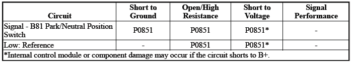
DTC P0851
Park/Neutral Position Switch Circuit Low Voltage
Diagnostic Fault Information
Typical Scan Tool Data
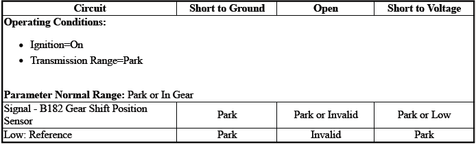
Transmission Range Switch
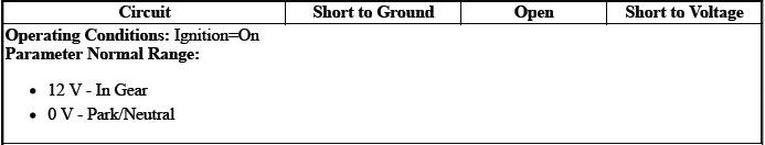
Park/Neutral Position Switch

Circuit/System Description
P0705, P0707, P0708
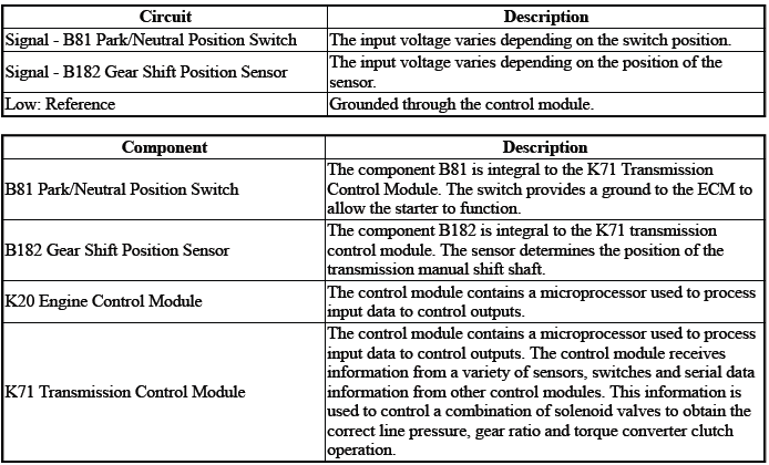
The sensor is an input to the control module K71. The control module K71 uses the information from the sensor signal B182 to determine what transmission gear range the vehicle operator selected.
The control module uses this data, along with other data, to adjust or control the following:
- Q23 Line Pressure Control Solenoid Valve
- Q27A Pressure Control Solenoid Valve 1
- Q27B Pressure Control Solenoid Valve 2
- Q27C Pressure Control Solenoid Valve 3
- Q27D Pressure Control Solenoid Valve 4
- Q27E Pressure Control Solenoid Valve 5
- Q27F Pressure Control Solenoid Valve 6
- Q27G Pressure Control Solenoid Valve 7{ If equipped }
- Q32A Shift Solenoid Valve 1
- Q32B Shift Solenoid Valve 2
- Q39A Torque Converter Clutch Pressure Control Solenoid Valve
P0851
The sensor is an input to the control module K20.
The control module uses this data, along with other data, to adjust or control the following: KR27 Starter Relay
Conditions for Running the DTC
P0705, P0707, P0708
- DTC P0851 = Not set
- K71 Transmission Control Module=Communication Enabled
- Ignition Voltage=10 to 16 V
- Service Mode=Disabled
Frequency the DTC runs=Continuously - After the running conditions are met
P0851
- Engine Torque= Greater than 75 Nm (55 lb ft)
- Ignition Voltage=10 to 16 V
- Selector Lever Position= P or N
- Throttle Position Sensor=Greater than 8%
- Vehicle Speed=Greater than 10 km/h (6 MPH)
Frequency the DTC runs=Continuously - After the running conditions are met
Conditions for Setting the DTC
P0705
Position 1 & Position 2=Not between 4.71 and 5.29 V - For greater than 1 s & For 2 consecutive events.
P0707
Position 1orPosition 2=Less than 0.127 V - For greater than 1 s & For 2 consecutive events.
P0708
Position 1orPosition 2=Greater than 4.87 V - For greater than 1 s & For 2 consecutive events.
P0851
Engine Control Module - Vehicle Speed Detected=Greater than 10 km/h (6 MPH) & Park/Neutral Position Switch=Park/Neutral - For greater than 2 s
Actions Taken When the DTC Sets
DTCs listed in the DTC Descriptor Category=Type A DTC - Exceptions listed below - Additional actions taken:
- Transmission Learn=Disabled
- Transmission gear allowed=3rd Gear - After a stop
- Engine Cranking=Disabled
DTC P0851=Type C DTC
Engine Cranking=Disabled
Conditions for Clearing the DTC
DTCs listed in the DTC Descriptor Category=Type A DTC - Exceptions listed below
DTC P0851=Type C DTC
Reference Information
Schematic: Reference
Refer to Automatic Transmission Controls Wiring Schematics
Connector End View: Reference
Refer to Component Connector End View Index
Component View: Reference
Refer to Disassembled Views
Description and Operation
- Refer to Electronic Component Description
- Refer to Transmission General Description
Electrical Information: Reference
- Refer to Circuit Testing
- Refer to Connector Repairs
- Refer to Testing for Intermittent Conditions and Poor Connections
- Refer to Wiring Repairs
DTC Type: Reference
Refer to Powertrain Diagnostic Trouble Code (DTC) Type Definitions
Scan Tool: Reference
Refer to Control Module: References
Circuit/System Verification
1. Ignition - On / Vehicle - In Service Mode
2. Verify there are no DTCs set related to the following system/component:K173 Transmission Range Control Module - If equipped
- If any DTC is set
Refer to: Diagnostic Trouble Code (DTC) List - Vehicle
- Go to next step: If no DTC is set
3. Transmission - Park
4. Verify the scan tool parameter: Park/Neutral Position Switch@K20 Engine Control Module=Park
- If not the specified state
Refer to Circuit/System Testing
- Go to next step: If the specified state
5. Transmission - Neutral - Brake Applied
6. Verify the scan tool parameter:Park/Neutral Position Switch@K20 Engine Control Module=Neutral
- If not the specified state
Refer to Circuit/System Testing
7. Transmission - Park
8. Verify the scan tool parameter: Transmission Range Switch@K71 Transmission Control Module=Park
- If not the specified state
Replace the component: K71 Transmission Control Module
- Go to next step: If the specified state
9. Operate the component: S3 Transmission Shift Lever
Verify the scan tool parameter: Transmission Range Switch=Matches the selector lever position
- If not the specified state
Replace the component:K71 Transmission Control Module
- Go to next step: If the specified state
10. Operate the vehicle within the Conditions for Running the DTC. You may also operate the vehicle within the conditions that you observed from the Freeze Frame/Failure Records data.
Verify the DTC does not set.
- If the DTC sets
Refer to Circuit/System Testing
- Go to next step: If the DTC is not set
11. All OK.
Circuit/System Testing
NOTE: Circuit/System Verification must be performed before proceeding with Circuit/System Testing.
1. Ignition/Vehicle & All vehicle systems - Off.
2. Disconnect the electrical connector:X1 @K71 Transmission Control Module.
3. Ignition - On / Vehicle - In Service Mode.
4. Test for greater than 9 V between the test points: Signal circuit terminal 5 & Ground.
- If less than 9 V
- Disconnect the electrical connector:X1@K20 Engine Control Module
- Test for infinite resistance between the test points: Signal circuit
terminal 5@Component harness &
Ground
- If less than infinite resistance
Repair the short to ground on the circuit.
- Go to next step: If infinite resistance
- If less than infinite resistance
- Test for less than 2 ohms between the test points:
- If 2 ohms or greater
Repair the open/high resistance in the circuit.
- If less than 2 ohms
Replace the component:K20 Engine Control Module
- If 2 ohms or greater
- Go to next step: If greater than 9 V
5. Ignition/Vehicle - Off.
6. Test for less than 1 V between the test points: Signal circuit terminal 5@Component harness & Ground.
- If 1 V or greater
Repair the short to voltage on the circuit.
- Go to next step: If less than 1 V
7. Test or replace the component: Park/Neutral Position Switch
Repair Instructions
Perform the Diagnostic Repair Verification after completing the repair: Refer to Diagnostic Repair Verification
- Refer to Transmission Control Module Replacement
- For control module replacement, programming, and setup: Refer to Control Module: References
READ NEXT:
 DTC P0711-P0713
Diagnostic Instructions
Perform the Diagnostic System Check prior to using this diagnostic
procedure: Refer to Diagnostic System
Check - Vehicle
Review the description of Strategy Based Diagnosi
DTC P0717, P07BF, or P07C0
Diagnostic Instructions
Perform the Diagnostic System Check prior to using this diagnostic
procedure: Refer to Diagnostic System
Check - Vehicle
Review the description of Strategy Based Diagnosi
DTC P0722, P077C, or P077D
Diagnostic Instructions
Perform the Diagnostic System Check prior to using this diagnostic
procedure: Refer to Diagnostic System
Check - Vehicle
Review the description of Strategy Based Diagnosi
SEE MORE:
DTC B370A
Diagnostic Instructions
Perform the Diagnostic System Check - Vehicle prior to using this
diagnostic procedure.
Review Strategy Based Diagnosis for an overview of the diagnostic
approach.
Diagnostic Procedure Instructions provide an overview of each diagnostic
category.
DTC Descriptor
DTC
Description and Operation
TIRE PRESSURE MONITOR DESCRIPTION AND OPERATION
WL - Wireless
WL - Wireless
WL - Wireless
WL - Wireless
P16 - P16 Instrument Cluster
P9 - P9 Driver Information Center Display
K9 - K9 Body Control Module
K77 - K77 Remote Control Door Lock Receiver
T10 - T10 Keyless Entry Antenna
B2LF - B2LF Tire Pre
