Buick Regal: DTC P0798, P0970, or P0971
Diagnostic Instructions
- Perform the Diagnostic System Check prior to using this diagnostic procedure: Refer to Diagnostic System Check - Vehicle
- Review the description of Strategy Based Diagnosis: Refer to Strategy Based Diagnosis
- An overview of each diagnostic category can be found here: Refer to Diagnostic Procedure Instructions
DTC Descriptor
DTC P0798
Pressure Control Solenoid Valve 3 Control Circuit
DTC P0970
Pressure Control Solenoid Valve 3 Control Circuit Low Voltage
DTC P0971
Pressure Control Solenoid Valve 3 Control Circuit High Voltage
Diagnostic Fault Information
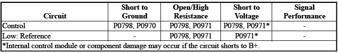
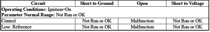
Typical Scan Tool Data
Pressure Control Solenoid Valve 3 Control Circuit High Voltage Test Status
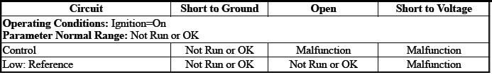
Pressure Control Solenoid Valve 3 Control Circuit Low Voltage Test Status
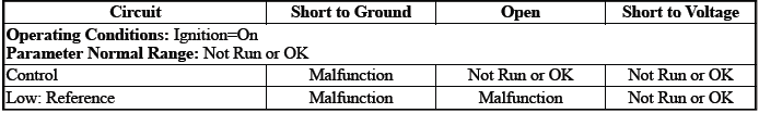
Pressure Control Solenoid Valve 3 Control Circuit Open Test Status
Circuit/System Description
For an overview of the component/system, refer to Transmission General Description
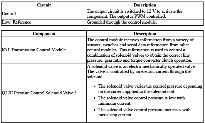
The solenoid valve controls the flow of transmission fluid to the hydraulic actuator that controls the C3 clutch.
Conditions for Running the DTC
- { P0798 }DTC P0606, P0657, P0962, P0963, P0966, P0967, P0970, P0971, P2720, P2721, P2729, P2730, P2738, P2739 = Not set
- { P0970 }DTC P0606, P0657, P0963, P0967, P0971, P2721, P2730, P2739 = Not set
- { P0971 }DTC P0606, P0657, P0962, P0966, P0970, P2720, P2729, P2738, = Not set
- Ignition Voltage=9 to 32 V
Frequency the DTC runs=Continuously - After the running conditions are met - For greater than 2 s
Conditions for Setting the DTC
P0798
Control Circuit=Commanded state does not match the actual state - For greater than 1 s
P0970
Control Circuit=Less than 20 mA - For greater than 1 s
P0971
Control Circuit=Greater than 1, 358 mA - For greater than 1 s
Actions Taken When the DTC Sets
DTCs listed in the DTC Descriptor Category=Type A DTC
- Learning=Disabled
- Fail-Safe Mode=Active
- Transmission gear allowed=3rd Gear - After a stop
Conditions for Clearing the DTC
DTCs listed in the DTC Descriptor Category=Type A DTC
Reference Information
Schematic: Reference
Refer to Automatic Transmission Controls Wiring Schematics.
Connector End View: Reference
Refer to Component Connector End View Index.
Component View: Reference
Refer to Disassembled Views.
Description and Operation
Electrical Information: Reference
- Refer to Circuit Testing
- Refer to Connector Repairs
- Refer to Testing for Intermittent Conditions and Poor Connections
- Refer to Wiring Repairs
DTC Type: Reference
Refer to Powertrain Diagnostic Trouble Code (DTC) Type Definitions.
Scan Tool: Reference
Refer to Control Module: References.
Circuit/System Verification
1. Ignition - On / Vehicle - In Service Mode
2. Perform the scan tool control function:Pressure Control Solenoid Valve 3 - Increase & Decrease
Verify the scan tool parameter:
- Pressure Control Solenoid Valve 3 Control Circuit High Voltage Test Status=Not Run or OK
- Pressure Control Solenoid Valve 3 Control Circuit Low Voltage Test Status=Not Run or OK
- Pressure Control Solenoid Valve 3 Control Circuit Open Test Status=Not Run or OK
- If not the specified state
Refer to Circuit/System Testing
- Go to next step: If the specified state
3. Perform the scan tool control function:Pressure Control Solenoid Valve 3 - Enable & Disable Verify the component produces a clicking sound:Q27C Pressure Control Solenoid Valve 3
- If the component does not produce a sound
Refer to Circuit/System Testing
- Go to next step: If the component produces a sound
4. Operate the vehicle within the Conditions for Running the DTC. You may also operate the vehicle within the conditions that you observed from the Freeze Frame/Failure Records data.
Verify the DTC does not set.
- If the DTC sets
Refer to Circuit/System Testing
- Go to next step: If the DTC is not set
5. All OK.
Circuit/System Testing
NOTE: It may take up to 2 min for all vehicle systems to power down before an accurate ground or low reference circuit continuity test can be performed.
1. Ignition/Vehicle & All vehicle systems - Off
NOTE: Twisting or tilting of the transmission control module electrical connector while disconnecting may result in bent or misaligned electrical terminal pins.
2. Remove the component:K71 Transmission Control Module
3. Test for 5.0 to 5.6 ohms between the test points:Control circuit terminal 3 & Low: Reference circuit terminal 4
- If not between 5.0 and 5.6 ohms
- Remove the component:Control Valve Body Cover
- Disconnect the electrical connector:Q27C Pressure Control Solenoid Valve 3
- Test for less than 2 ohms between the test points:
- Control circuit terminal 2@Component harness & Control circuit terminal 3@Control module harness
- Low: Reference circuit terminal 1@Component harness & Low: Reference circuit terminal 4@Control module harness
- If 2 ohms or greater - Replace the component:Automatic Transmission Wiring Harness
- If less than 2 ohms - Replace the component:Q27C Pressure Control Solenoid Valve 3
- Go to next step: If between 5.0 and 5.6 ohms
4. Test for infinite resistance between the test points:
- Control circuit terminal 3 & Transmission Case
- Low: Reference circuit terminal 4 & Transmission Case
- If less than infinite resistance
- Remove the component:Control Valve Body Cover
- Disconnect the electrical connector:Q27C Pressure Control Solenoid Valve 3
- Test for infinite resistance between the test points:
- Control circuit terminal 2@Component harness & Transmission Case
- Low: Reference circuit terminal 1@Component harness & Transmission Case
- If less than infinite resistance - Replace the component:Automatic Transmission Wiring Harness
- If infinite resistance - Replace the component:Control Valve Body
- Go to next step: If infinite resistance
5. Replace the component:K71 Transmission Control Modul
Component Testing
1. Ignition/Vehicle - Off
2. Disconnect the electrical connector:Q27C Pressure Control Solenoid Valve 3
NOTE: The component's temperature should be 19 to 21ºC (66 to 70ºF) while testing.
3. Test for 5.0 to 5.6 ohms between the test points:Control terminal 2 & Low: Reference terminal 1
- If not between 5.0 and 5.6 ohms
Replace the component:Control Valve Body
- Go to next step: If between 5.0 and 5.6 ohms
4. Test for infinite resistance between the test points:Each terminal of the component & The component's housing
- If less than infinite resistance
Replace the component:Control Valve Body
- Go to next step: If infinite resistance
5. All OK.
Repair Instructions
Perform the Diagnostic Repair Verification after completing the repair: Refer to Diagnostic Repair Verification
- Refer to Control Valve Body Replacement
- Refer to Wiring Harness Wire Replacement
- For control module replacement, programming, and setup: Refer to Control Module: References
READ NEXT:
 DTC P0815, P0816, or P0826
Diagnostic Instructions
Perform the Diagnostic System Check prior to using this diagnostic
procedure: Refer to Diagnostic System
Check - Vehicle
Review the description of Strategy Based Diagnosi
DTC P0973 or P0974
Diagnostic Instructions
Perform the Diagnostic System Check prior to using this diagnostic
procedure: Refer to Diagnostic System
Check - Vehicle
Review the description of Strategy Based Diagnosi
DTC P0976 or P0977
Diagnostic Instructions
Perform the Diagnostic System Check prior to using this diagnostic
procedure: Refer to Diagnostic System
Check - Vehicle
Review the description of Strategy Based Diagnosi
SEE MORE:
DTC B260B or B260C
Diagnostic Instructions
Perform the Diagnostic System Check - Vehicle prior to using this
diagnostic procedure.
Review Strategy Based Diagnosis for an overview of the diagnostic
approach.
Diagnostic Procedure Instructions provides an overview of each
diagnostic category.
DTC Descriptors
D
DTC B018A, B048C, B048F, or B1395
Diagnostic Instructions
Perform the Diagnostic System Check - Vehicle prior to using this
diagnostic procedure.
Review Strategy Based Diagnosis for an overview of the diagnostic
approach.
Diagnostic Procedure Instructions provides an overview of each
diagnostic category.
DTC Descriptors
D
