Buick Regal: Rear Shock Absorber Mount Replacement
.png)
Preliminary Procedures
1. Remove the rear tire and wheel assembly.
2. Shock Absorber Replacement (GNC)Shock Absorber Replacement (GNQ).
- CAUTION: Refer to Fastener Caution.
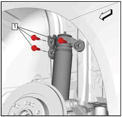
Rear Shock Absorber NutTighten 20 N.m (15 lb ft) - Rear Suspension Mount Upper Cup
- Rear Shock Absorber Mount
- Rear Shock Absorber
SHOCK ABSORBER REPLACEMENT (GNC)
Removal Procedure
1. Remove the tire and wheel assembly.
2. Rear Wheelhouse Liner - Remove.
3.
.png)
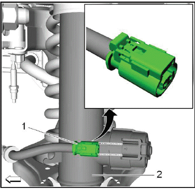
{ If equipped }Electrical Connector(1)@Shock Absorber(2) - Disconnect.
4.
.png)
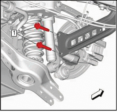
5. Rear Shock Absorber Nut(1) - Remove.
6. Rear Shock Absorber Bolt(2) - Remove and DISCARD.
7.
Rear Shock Absorber Bolt(1) - Remove[3x].
8.
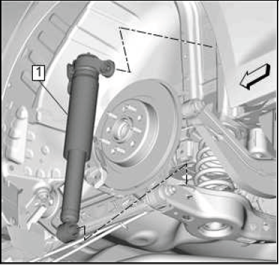
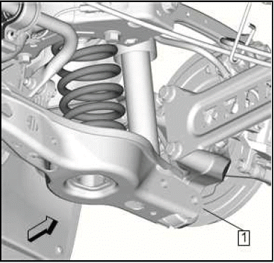
Rear Shock Absorber(1) - Remove.
Installation Procedure
1.
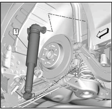
Rear Shock Absorber(1) - Install.
2.
.png)
CAUTION: Fastener Caution.
NOTE: Ensure jounce bumper and dust cover are secure within the top mount before tightening. If not properly secure, the jounce bumper and dust cover will fall down causing a click noise. When the top mount is fastened it secures the jounce bumper within the top mount.
Rear Shock Absorber Bolt(1) - Install and tighten[3x]58N.m (43 lb ft).
3. Tug downwards on the jounce bumper and dust cover. If the assembly falls out of the mount, remove the top mount fasteners and start over.
4.
.png)
CAUTION: This vehicle is equipped with torque-to-yield or single use
fasteners. Install a
NEW torque-to-yield or single use fastener when installing this component.
Failure to replace the torque-to-yield or single use fastener could cause
damage to the vehicle or component.
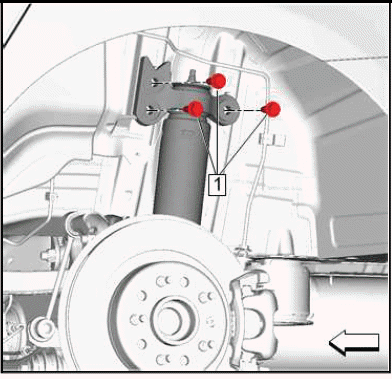
Rear Shock Absorber Bolt(2) - Install NEW.
5. Rear Shock Absorber Nut(1) - Install and tighten
- First Pass: 160 N.m (118 lb ft)
- Final Pass: 90 - 105 degrees
6.
.png)
{ If equipped }Electrical Connector(1)@Shock Absorber(2) - Connect.
7. Rear Wheelhouse Liner - Install.
8. Install the tire and wheel assembly.
SHOCK ABSORBER REPLACEMENT (GNQ)
Removal Procedure
1. Remove the rear tire and wheel assembly.
2. Rear Wheelhouse Liner - Remove.
3.
.png)
If equipped Electrical Connector(1)@Shock Absorber(2) - Disconnect.
4. Using a suitable jack stand support the lower control arm.
5.
.png)
Rear Shock Absorber Nut(1) - Remove.
6. Rear Shock Absorber Bolt(2) - Remove and DISCARD.
7.
.png)
Rear Shock Absorber Bolt(1) - Remove[3x].
8.
.png)
Rear Shock Absorber(1) - Remove.
Installation Procedure
1.
.png)
Rear Shock Absorber(1) - Install.
2.
CAUTION: Refer to Fastener Caution.
NOTE: Ensure jounce bumper and dust cover are secure within the top mount before tightening. If not properly secure, the jounce bumper and dust cover will fall down causing a click noise. When the top mount is fastened it secures the jounce bumper within the top mount.
Rear Shock Absorber Bolt(1) - Install and tighten[3x] 58 N.m (43 lb ft).
3. Tug downwards on the jounce bumper and dust cover. If the assembly falls out of the mount, remove the top mount fasteners and start over.
4.
CAUTION: This vehicle is equipped with torque-to-yield or single use fasteners. Install a NEW torque-to-yield or single use fastener when installing this component.
Failure to replace the torque-to-yield or single use fastener could cause damage to the vehicle or component.
Rear Shock Absorber Bolt(2) - Install NEW.
5. Rear Shock Absorber Nut(1) - Install.
Tighten
- First Pass: 100 N.m (74 lb ft)
- Final Pass: (90 - 105 degrees)
6. Remove the support from the lower control arm.
7.
If equipped Electrical Connector(1)@Shock Absorber(2) - Connect.
8. Rear Wheelhouse Liner - Install.
9. Install the rear tire and wheel assembly.
TRAILING ARM REPLACEMENT
Removal Procedure
1. Raise and support the vehicle.
2. Remove the rear tire and wheel assembly.
3. Rear Tire Front Air Deflector - Remove.
4. Support the rear suspension lower control arm with an appropriate jack stand.
5.
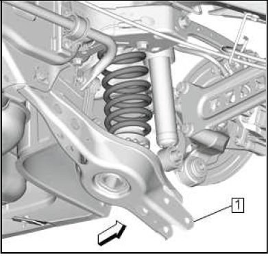
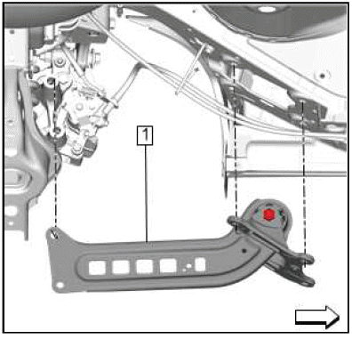
Lower the rear suspension lower control arm (1) to provide clearance for the rear suspension trailing arm bolt.
6.

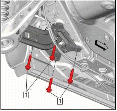
Rear Suspension Trailing Arm Bolt(1) - Remove and DISCARD[2x].
7.
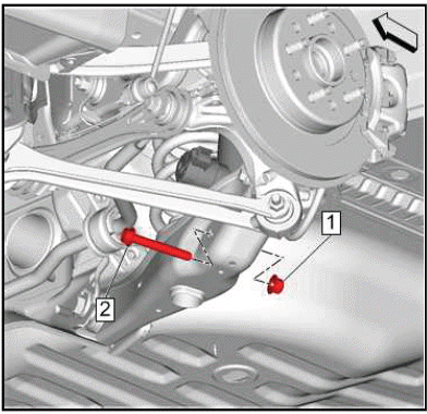
Rear Suspension Trailing Arm Bracket Bolt(1) - Remove and DISCARD[4x].
8.

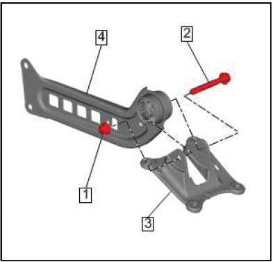
Rear Suspension Trailing Arm and Bracket(1) - Remove.
9. Mark the relationship between the rear suspension trailing arm (1) and the rear suspension trailing arm bracket.
10.
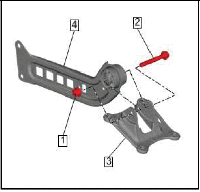
Rear Suspension Trailing Arm Bracket Nut(1) - Remove.
11. Rear Suspension Trailing Arm Bracket Bolt(2) - Remove and DISCARD.
12. Separate the rear suspension trailing arm bracket (3) from the rear suspension trailing arm (4).
Installation Procedure
1. If the rear suspension trailing arm or rear suspension trailing arm bracket are being replaced, transfer the relationship marks made on the old components to the new components.
2.
Position the rear suspension trailing arm (4) into the rear suspension trailing arm bracket (3) aligning the relationship marks previously made.
CAUTION: This vehicle is equipped with torque-to-yield or single use fasteners. Install a NEW torque-to-yield or single use fastener when installing this component.
Failure to replace the torque-to-yield or single use fastener could cause damage to the vehicle or component.
3. Rear Suspension Trailing Arm Bracket Bolt(2) - Install NEW.
CAUTION: Refer to Fastener Caution.
4. Rear Suspension Trailing Arm Bracket Nut(1) - Install and tighten.
- First Pass: 160 N.m (118 lb ft)
- Final Pass: (90 - 105 degrees)
5.
Rear Suspension Trailing Arm and Bracket(1) - Install.
6.
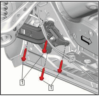
Rear Suspension Trailing Arm Bracket Bolt(1) - Install NEW and tighten[4x]
- First Pass: 100 N.m (74 lb ft)
- Final Pass: (90 - 105 degrees)
7.
Rear Suspension Trailing Arm Bolt(1) - Install NEW and tighten[2x]
- First Pass: 160 N.m (118 lb ft)
- Final Pass: (90 - 105 degrees)
8.
Raise the rear suspension lower control arm (1) back into position and install.
9. Remove the jack stand from underneath the rear suspension lower control arm.
10. Rear Tire Front Air Deflector - Install.
11. Install the rear tire and wheel assembly.
12. Remove the support and lower the vehicle.
READ NEXT:
 Adjust Link Replacement (FWD)
Removal Procedure
1. Remove the tire and wheel assembly.
2. Rear Wheel Speed Sensor Replacement (Front Wheel Drive) Rear Wheel Speed
Sensor Replacement
(All Wheel Drive) - Remove.
3.
Rear Suspension
Rear Spring Replacement (FWD)
Removal Procedure
1. Remove the rear tire and wheel assembly.
2.
Rear Stabilizer Shaft Link Nut(1) - Remove.
3. Rear Stabilizer Shaft Link Bolt(2) - Remove.
4.
Rear Shock Absorber Nut(1) - Remove
Rear Suspension Upper Lateral Link Replacement (FWD)
Removal Procedure
1. Remove the tire and wheel assembly.
2. { If equipped }Rear Suspension Position Ball Socket @Rear Suspension Upper
Lateral Link - Disconnect.
3.
Rear Suspension Upper Lateral Li
SEE MORE:
DTC P127C, P128A, P128B, P16E4, or P16E5
Diagnostic Instructions
Perform the Diagnostic System Check - Vehicle prior to using this
diagnostic procedure.
Review Strategy Based Diagnosis for an overview of the diagnostic
approach.
Diagnostic Procedure Instructions provides an overview of each
diagnostic category.
DTC Descriptors
D
Forward Collision Alert (FCA)
System
If equipped, the FCA system may
help to avoid or reduce the harm
caused by front-end crashes. When
approaching a vehicle ahead too
quickly, FCA provides a red flashing
alert on the windshield and rapidly
beeps. FCA also lights an amber
visual alert if following another
vehicle much too closely.
FCA
