Buick Regal: Torque Converter and Differential Housing Assembly Assemble
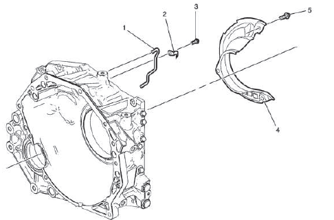
- Front Differential Transfer Drive Gear Fluid Passage Tube
- Lubricant Fluid Hose Clamp
- Automatic Transmission Fluid Baffle Bolt
CAUTION: Refer to Fastener Caution.
Tighten 7 N.m (62 lb in)
- Automatic Transmission Fluid Baffle
- Automatic Transmission Fluid Baffle Bolt [2x]
Tighten 7 N.m (62 lb in)
TORQUE CONVERTER AND DIFFERENTIAL HOUSING INSTALLATION
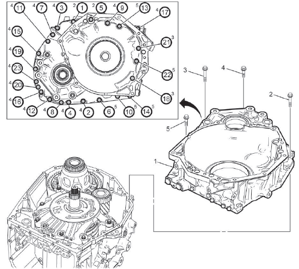
Fig. 4: Torque Converter And Differential Housing Bolts Tightening Sequence
- Torque Converter and Differential Housing
Procedure
Install a bead of sealant around the perimeter of the torque converter and differential housing mating surface: Refer to Adhesives, Fluids, Lubricants, and Sealers.
- Torque Converter Housing Bolt[2x] M10 x 40
CAUTION: Refer to Fastener Caution.
Tighten in sequence 35 N.m (26 lb ft)
- Torque Converter Housing Bolt[2x] M8 x 35
Tighten in sequence 29 N.m (21 lb ft)
- Torque Converter Housing Bolt[14x] M8 x 39
Tighten in sequence 29 N.m (21 lb ft)
- Torque Converter Housing Bolt [5x] M8 x 30
Tighten in sequence 29 N.m (21 lb ft)
INPUT SPEED SENSOR INSTALLATION
- Automatic Transmission Input Speed Sensor
- Automatic Transmission Input Speed Sensor Bolt
CAUTION: Refer to Fastener Caution.
Tighten 5 N.m (44 lb in)
CONTROL VALVE BODY ASSEMBLY INSTALLATION
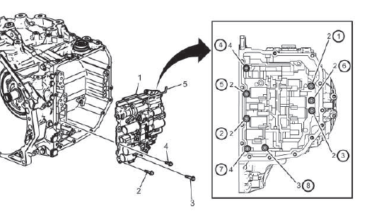
- Control Valve Body - Model Dependent
NOTE: For models with start/stop, Electronic Component Description.
- Valve Body Bolt [5x] M6 x 21
CAUTION: Refer to Fastener Caution.
Tighten 10 N.m (89 lb in)
- Valve Body Bolt[1x] M6 x 51
Tighten 10 N.m (89 lb in)
- Valve Body Bolt[2x] M6 x 31
Tighten 10 N.m (89 lb in)
- Manual Valve Link
NOTE: Ensure you reconnect the manual valve link.
WIRING HARNESS INSTALLATION
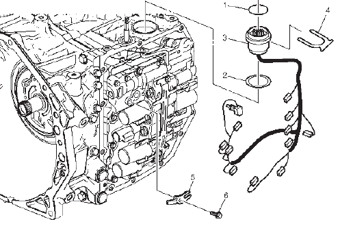
- Automatic Transmission Wiring Connector Seal
- Automatic Transmission Wiring Connector Seal
- Wiring Harness Wire
NOTE: Tab on wiring harness connector fits in slot on case to insure alignment of transmission control module (TCM).
- Automatic Transmission Wiring Harness Retainer
- Automatic Transmission Fluid Temperature Sensor Clip
- Automatic Transmission Fluid Temperature Sensor Bolt
Procedure
Connect the wiring harness connectors to the control valve body in proper location as mark when removed.
Tighten 7 N.m (62 lb in)
CONTROL VALVE BODY COVER INSTALLATION
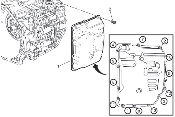
Fig. 5: Automatic Transmission Valve Body Control Unit Cover Bolts Tightening
Sequence
- Control Valve Body Cover
Procedure
Install a bead of sealant around the perimeter of the case to valve body cover mating surface: Refer to Adhesives, Fluids, Lubricants, and Sealers.
- Control Valve Body Cover Bolt [13x]
CAUTION: Refer to Fastener Caution.
Tighten in sequence 13 N.m (115 lb in)
TRANSMISSION FLUID FILLER OVERFLOW TUBE AND DRAIN PLUG INSTALLATION
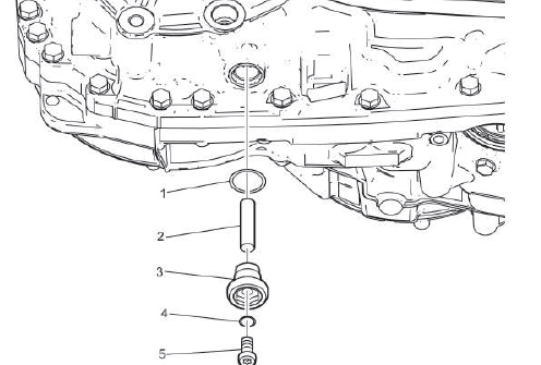
- Transmission Oil Level Check Plug Seal
NOTE: Install a NEW seal. Do NOT reuse the old seal.
- Transmission Fluid Filler Upper Tube
- Transmission Oil Level Check Plug Seal
CAUTION: Refer to Fastener Caution.
Tighten 47N.m (35 lb ft)
- Transmission Oil Drain Plug Seal
NOTE: Install a NEW seal. Do NOT reuse the old seal.
- Transmission Oil Drain Plug
Tighten 7N.m (62 lb in)
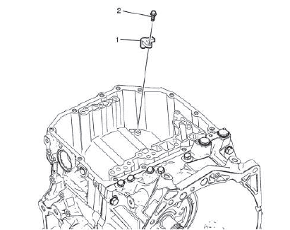
TRANSMISSION CONTROL MODULE INSTALLATION
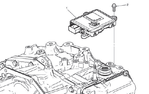
- Transmission Control Module
- Transmission Control Module Bolt [3x]
CAUTION: Refer to Fastener Caution.
Tighten 25N.m (18 lb ft)
TORQUE CONVERTER FLUID SEAL INSTALLATION
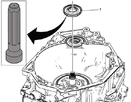
- Torque Converter Fluid Seal
Procedure
Install seal with hand, then finish by tapping around perimeter with rubber mallet until properly seated.
NOTE: Install a NEW seal. Do NOT reuse the old seal.
TORQUE CONVERTER ASSEMBLY INSTALLATION
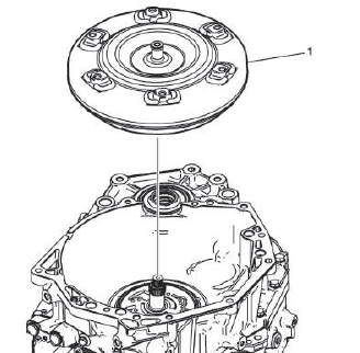
- Torque Converter
READ NEXT:
 Transmission Identification Information
For automatic transmission AF50, the identification plate is on the top of
the transmission housing.
Aisin Warner transmission type
Fabrication line 1 = 000001 - 500000 Fabrication line 2 = 50000
Electronic Component Description
Control Module
K71 Transmission Control Module
The TCM (2) is mounted directly on top of the transmission (1). The selector
lever and transmission range sensor is
integrated in the control module. T
SEE MORE:
DTC C0293
Diagnostic Instructions
Perform the Diagnostic System Check prior to using this diagnostic
procedure: Diagnostic
System Check - Vehicle
Review the description of Strategy Based Diagnosis: Strategy Based
Diagnosis
An overview of each diagnostic category can be found here: Diagnostic
Proced
Compact Spare Tire
Warning:
Driving with more than one
compact spare tire at a time could
result in loss of braking and
handling. This could lead to a
crash and you or others could be
injured. Use only one compact
spare tire at a time.
If this vehicle has a compact spare
tire, it was fully inflated when new;
however,
