Buick Regal: Camshaft Position Actuator and Camshaft Replacement - Exhaust
Special Tools
- EN-50656 Holding Tool
- EN 50793 Locking Tool
For equivalent regional tools, refer to Special Tools.
Removal Procedure
NOTE: Ensure the engine is properly timed to Top Dead Center (TDC), prior to performing repairs.
1. Remove the camshaft cover. Refer to Camshaft Cover Replacement.
2.
.png)
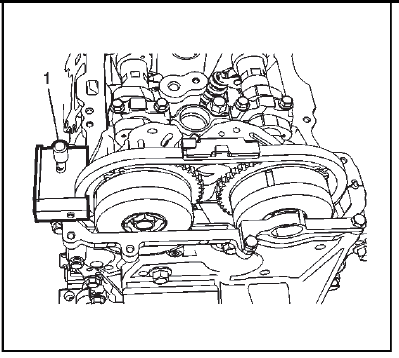
NOTE: Ensure the EN-50656 Holding tool is installed and securely tightened to prevent the camshaft chain from dropping into the front engine cover during camshaft actuator replacement.
Install EN-50656 timing chain holding tool (1) and tighten to 8 N.m (71 lb in).
3.
.png)
NOTE: Ensure to mark actuator sprocket and chain before removal.
Align and install camshaft actuator locking tool (2) EN 50793 into the slots of the exhaust camshaft actuator and mount tool to engine front cover assembly and tighten the bolts (1) to 10 N.m (89 lb in).
4.
.png)
Remove and DISCARD the camshaft actuator bolt (1).
5.
.png)
Remove the EN-50793 holding tool (2).
6.
.png)
Remove the upper timing chain guide bolts (1, 2).
7. Remove the upper timing chain guide (3).
8. Remove the camshaft front bearing cap bolts (4).
NOTE: Locate the pry points (6) in the camshaft front bearing cap. When using the 3 pry points to remove the front bearing cap evenly, use a protective material between the camshaft lobes, the cylinder head flange, and pry tool.
9. Remove the camshaft front bearing cap (5).
10.
.png)
Mark the exhaust camshaft rear cap to ensure it is installed in the same position. Remove the exhaust camshaft bearing rear cap bolts (1) and cap (2).
NOTE: Loosen each bolt on each cap one turn at a time until there is no spring tension pushing on the camshaft.
11. Mark the camshaft caps (4) to ensure they are installed in the same position.
12. Remove the exhaust camshaft cap bolts (3).
13. Remove the camshaft caps (4).
14.
.png)
Pull exhaust camshaft actuator assembly forward away from camshaft assembly (1), then lift rear of exhaust camshaft assembly to a tilt and pull free from exhaust camshaft actuator assembly (2).
NOTE: If replacing the camshaft, ensure to transfer any marking from the old camshaft to the new one.
15. Replace the camshaft if necessary.
Installation Procedure
1.
.png)
Install the exhaust camshaft (1) and camshaft actuator (2).
2.
.png)
Align and install camshaft actuator locking tool (2) EN 50793 into the slots of the intake camshaft actuator and mount tool to engine front cover assembly and tighten the bolts (1) to 10 N.m (89 lb in).
3.
.png)
Install a NEW camshaft actuator bolt (1) and tighten to 30 N.m (22 lb ft) plus 100 degrees.
4.
.png)
NOTE: Apply lubricant to all lobes and journals prior to installing the camshafts.
Set the exhaust camshaft on top of the roller followers in the camshaft bearing journals with the exhaust actuator timing mark at approximately the one O'clock position.
NOTE: To properly position the camshaft caps, install the camshaft cap bolts into the camshaft caps prior to installing the camshaft caps on the camshafts.
5. Install the camshaft cap bolts (1, 3) into the camshaft caps (2, 4).
6. Install the camshaft caps (2, 4) and hand start the camshaft cap bolts (1, 3).
7.
.png)
Install the front camshaft bearing cap (1). Install the timing chain guide (2) onto the front camshaft bearing cap, then hand start the camshaft cap bolts (3 - 5).
8.
.png)
NOTE: During the tightening sequence, locate and tighten each camshaft cap bolt installed into the circular hole first. Then, tighten the bolt installed into the slotted hole.
Install the camshaft cap bolts in sequence using the following procedure:
- Tighten the camshaft cap bolts in sequence to 8 N.m (71 lb in).
- Loosen both bolts in each cap in sequence to 180 degrees.
- Tighten the camshaft cap bolts in sequence to 10 N.m (89 lb in) twice.
9.
.png)
Tighten the front camshaft cap bolts in sequence to 10 N.m (89 lb in) twice.
10.
Remove EN-50656 timing chain holding tool (1).
11. Install the camshaft cover. Refer to Camshaft Cover Replacement.
CAMSHAFT COVER HEAT SHIELD REPLACEMENT
Preliminary Procedures
1. Intake Manifold Cover Replacement.
2. Turbocharger Heat Shield Replacement.
3. Disconnect and reposition the engine wiring harness.
- Camshaft Cover Heat Shield Bolt [4x]
CAUTION: Refer to Fastener Caution.
Tighten 10 N.m (89 lb in) - Camshaft Cover Heat Shield
Procedure
Disconnect the camshaft position actuator solenoid valve.
NOTE: When removing the camshaft cover heat shield, carefully guide the shield past the turbocharger coolant return and PCV pipes.
VALVE STEM OIL SEAL AND VALVE SPRING REPLACEMENT
Special Tools
- EN-37281-A Valve Guide Seal Remover
- EN-50717 Valve Spring Compressor
- EN-50792 Flywheel Holding Tool
Equivalent regional tools: Special Tools
Removal Procedure
NOTE: Prevent the crankshaft from rotating clockwise or counterclockwise before using compressed air in the cylinder. Rotation of the crankshaft may cause damage to EN-50792 Flywheel Holding Tool.
1. If equipped with a manual transmission, leave the transmission in first gear with the vehicle on the ground and the parking brake set.
2. If equipped with an automatic transmission, remove the starter.
4. Remove the camshaft.
5. Valve Rocker Arm - Remove
6.
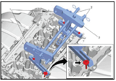
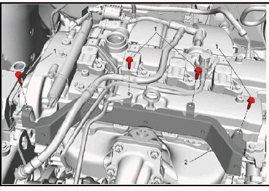
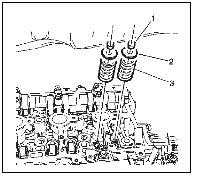
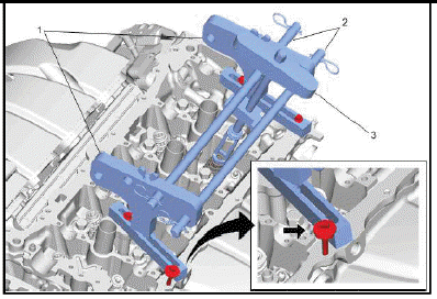
NOTE: When mounting the valve spring compressor to the cylinder head, a suitable large washer should be used as indicated by the arrow.
Install the EN-50717 Valve Spring Compressor (1) to the front and rear of the cylinder head as shown.
7. Install the cross bars and locks (2) of the EN-50717 Valve Spring Compressor to the valve spring compressor adaptors.
8. Remove the spark plugs.
9. Install an air hose adapter into the spark plug hole.
10. Attach an air hose to the adapter and pressurize the cylinder to 690 kPa (100 psi).
11. Compress the valve spring using the valve spring compressor (3).
12.
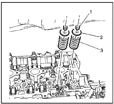
Remove the valve spring keepers (1).
13. Remove the valve spring (3) and retainer (2).
14. Use the EN-37281-A Valve Guide Seal Remover to remove the valve seal.
Installation Procedure
1. Using the EN-37281-A Valve Guide Seal Remover, install the NEW valve seal. Fully seat the seal onto the valve guide.
2.
Install the valve spring (3) and retainer (2).
3. Compress the valve spring using the valve spring compressor.
4. Install the valve spring keepers (1).
5. Disconnect the air hose and air hose adapter.
6.
Remove the EN-50717 Valve Spring Compressor and EN-50717 Valve Spring Compressor adapter set from the cylinder head.
7. Install the spark plugs.
8. Valve Rocker Arm - Install.
9. Install the camshaft.
10. Remove the EN-50792 Flywheel Holding Tool.
11. If equipped with an automatic transmission, install the starter.
READ NEXT:
 Cylinder Head Replacement
Removal Procedure
Special Tools
EN-38188 Cylinder Head Broken Bolt Extractor Kit - or equivalent
aftermarket tool
EN-45059 Angle Meter
EN-36857 Engine Lift Bracket
Equivalent regional tools: Sp
Automatic Transmission Flex Plate Replacement
Special Tools
EN-45059 Angle Meter
EN-50792 Holding Tool
Equivalent regional tools: Special Tools
Removal Procedure
1. Remove the transmission.
2.
To prevent crankshaft rotation, install the EN
Engine Replacement
Removal Procedure
1. Upper Intermediate Steering Shaft - Remove.
2. Recover the refrigerant. Refrigerant Recovery and Recharging (R-1234yf).
3. Drain the coolant. Cooling System Draining and Filling
SEE MORE:
DTC P2734, P2738, or P2739
Diagnostic Instructions
Perform the Diagnostic System Check prior to using this diagnostic
procedure: Refer to Diagnostic System
Check - Vehicle
Review the description of Strategy Based Diagnosis: Refer to Strategy
Based Diagnosis
An overview of each diagnostic category can be found here: R
DTC B3935
Diagnostic Instructions
Perform the Diagnostic System Check - Vehicle prior to using this
diagnostic procedure.
Review Strategy Based Diagnosis for an overview of the diagnostic
approach.
Diagnostic Procedure Instructions provides an overview of each
diagnostic category.
DTC Descriptor
DT
