Buick Regal: Vent Hose Replacement
Removal Procedure
1. Raise and support the vehicle. Lifting and Jacking the Vehicle.
2.
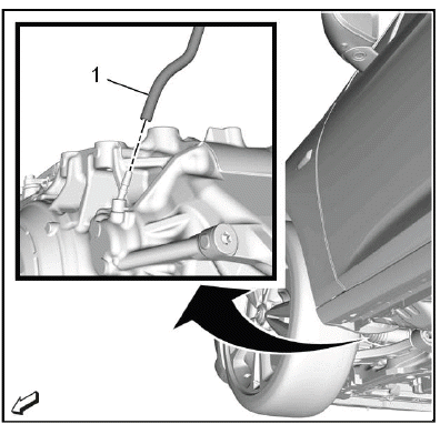
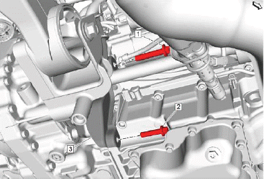
Transmission Vent Hose (1) @Transmission - Disconnect.
3. Lower the vehicle.
4.
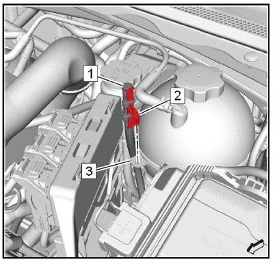
Unclip the vent hose retainer (2) from the radiator surge tank (3).
NOTE: Note the routing of the vent hose.
5. Transmission Vent Hose (1) - Remove.
Installation Procedure
1.
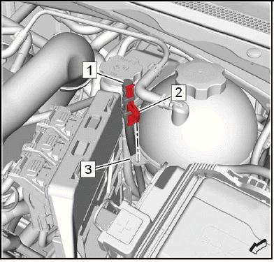
NOTE: Ensure the vent hose is free of kinks and routed clear of sharp objects.
Transmission Vent Hose (1) - Install.
2. Clip the vent hose retainer (2) in the radiator surge tank (3).
3. Raise the vehicle.
4.
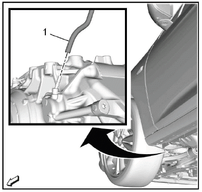
Transmission Vent Hose (1) @Transmission - Connect.
5. Lower the vehicle.
TORQUE CONVERTER FLUID SEAL REPLACEMENT
Special Tools
- DT-586 Remover Hook
- DT-21128 Pinion Seal Installer
- GE-6125 - 1B Slide Hammer
Equivalent regional tools: Refer to Special Tools
Removal Procedure
1. Transmission - Remove - Refer to Transmission Replacement.
2. Torque Converter - Remove - Refer to Torque Converter Replacement.
3.
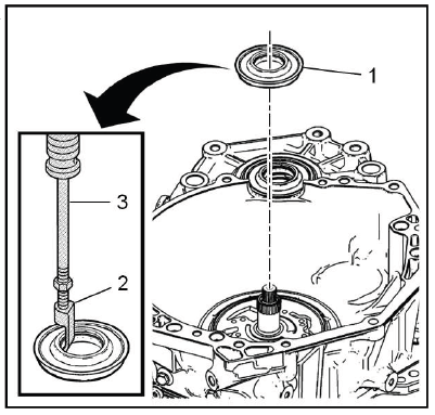
Torque Converter Fluid Seal (1) - Remove and DISCARD - Use the special tool: GE-6125 - 1B slide hammer (3) & DT-586 hook (2)
Installation Procedure
1.
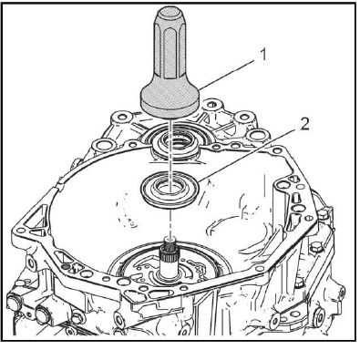
Torque Converter Fluid Seal (2) - Install NEW - Use the special tool: DT-21128 installer (1).
2. Torque Converter - Install - Refer to Torque Converter Replacement.
3. Transmission - Install - Refer to Transmission Replacement.
4. Reset the learned values of the transmission control module. Learned Values Reset.
5. Learn the gear selector neutral position. Gear Selector -N- Position Learn.
TRANSMISSION CONVERTER COVER REPLACEMENT
Preliminary Procedure
Refer to Lifting and Jacking the Vehicle.
- Transmission Rear Bolt
CAUTION: Tighten the transmission converter cover carefully to prevent it from becoming deformed. A deformed transmission converter cover may wear on the starting ring gear or the front wheel drive shaft resulting in noise emission and improper protecting properties.
CAUTION: Refer to Fastener Caution
Tighten 60N.m (44 lb ft)
- Transmission Lower Bolt
CAUTION: Tighten the transmission converter cover carefully to prevent it from becoming deformed. A deformed transmission converter cover may wear on the starting ring gear or the front wheel drive shaft resulting in noise emission and improper protecting properties.
Tighten 40N.m (30 lb ft)
- Transmission Converter Cover
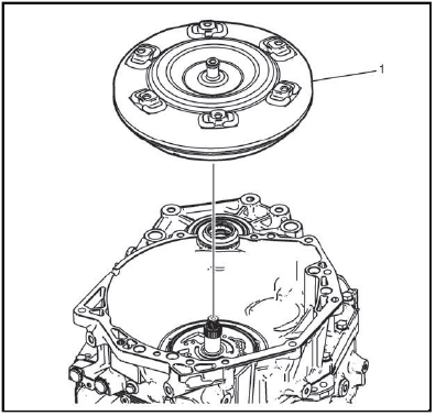
TORQUE CONVERTER REPLACEMENT
Removal Procedure
1. Transmission - Remove - Refer to Transmission Replacement.
2.
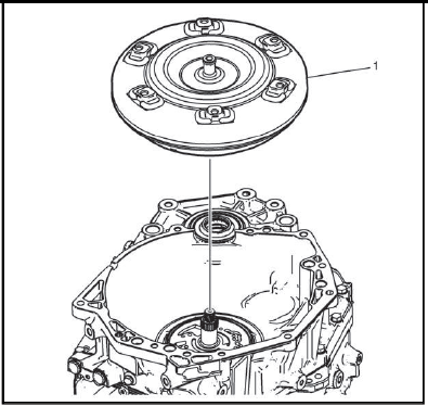
Torque Converter (1) @Transmission - Remove.
Installation Procedure
1.
Torque Converter (1) @Transmission - Install.
2. Transmission - Install - Refer to Transmission Replacement.
3. Reset the learned values of the transmission control module. Learned Values Reset.
4. Learn the gear selector neutral position. Gear Selector -N- Position Learn.
READ NEXT:
 Input Speed Sensor Replacement
Removal Procedure
1. Control Valve Body - Remove - Refer to Control Valve Body Replacement.
2.
Input Speed Sensor Bolt (1) - Remove.
3. Input Speed Sensor (2) - Remove.
Installation Procedure
1.
In
Front Wheel Drive Shaft Seal Replacement - Left Side
Special Tools
DT-446 Seal Installer
EN-45000 Seal Remover
Equivalent regional tools: Refer to Special Tools
Removal Procedure
1. Raise and support the vehicle.
2. Front Wheel Drive Half Shaft- Le
Wiring Harness Wire Replacement
Removal Procedure
1. Transmission Control Module - Remove - Refer to Transmission Control
Module Replacement.
2. Drain the transmission fluid. Transmission Fluid Drain and Fill.
3. Control Valve Bo
SEE MORE:
DTC C0670 or C0675
Diagnostic Instructions
Perform the Diagnostic System Check - Vehicle prior to using this
diagnostic procedure.
Review Strategy Based Diagnosis for an overview of the diagnostic
approach.
Diagnostic Procedure Instructions provides an overview of each
diagnostic category.
DTC Descriptors
D
Older Children
Older children who have outgrown
booster seats should wear the
vehicle's seat belts.
The manufacturer instructions that
come with the booster seat state the
weight and height limitations for that
booster. Use a booster seat with a
lap-shoulder belt until the child
passes the fit test below:
Sit a
