Buick Regal: Range Selector Lever Cable Adjustment
Removal Procedure
1. Battery Tray - Remove - Refer to Battery Tray Replacement.
Adjustment Procedure
1.
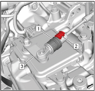
Push the secure ring (1) against the spring force forwards.
2. Lift the range selector lever cable retainer (2) in order to remove the mechanical connection between transmission control and transmission.
3. Ensure that the range selector lever cable lever (3) is in position "P".
4.
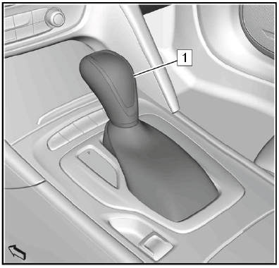
Ensure that the transmission control lever (1) is in position "P".
5.
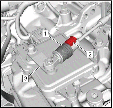
Push the secure ring (1) against the spring force forwards.
6. Install the range selector lever cable retainer (2) in order to install the mechanical connection between the transmission control and the transmission.
7. The secure ring must flip backwards and secure the range selector lever cable retainer.
Installation Procedure
1. Battery Tray - Install - Refer to Battery Tray Replacement.
RANGE SELECTOR LEVER CABLE BRACKET REPLACEMENT
Preliminary Procedures
1. Refer to Battery Tray Replacement.
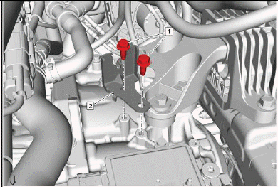
2. Range Selector Lever Cable@Range Selector Lever Cable Lever & Transmission Range Selector Lever Cable Bracket - Remove - Refer to Range Selector Lever Cable Replacement.
- Transmission Range Selector Lever Cable Bracket Bolt[2x]
CAUTION: Refer to Fastener Caution
Tighten 22N.m (16 lb ft)
- Transmission Range Selector Lever Cable Bracket
Procedure
Refer to Range Selector Lever Cable Adjustment
READ NEXT:
 Transmission Control Lever Knob Replacement
Removal Procedure
1. Set the parking brake.
2. Shift the transmission control lever into Reverse position.
3.
Gently release the transmission control lever boot bezel (1) at the front.
Unclip 6 re
Vent Hose Replacement
Removal Procedure
1. Raise and support the vehicle. Lifting and Jacking the Vehicle.
2.
Transmission Vent Hose (1) @Transmission - Disconnect.
3. Lower the vehicle.
4.
Unclip the vent hose retain
Input Speed Sensor Replacement
Removal Procedure
1. Control Valve Body - Remove - Refer to Control Valve Body Replacement.
2.
Input Speed Sensor Bolt (1) - Remove.
3. Input Speed Sensor (2) - Remove.
Installation Procedure
1.
In
SEE MORE:
Front Wheel Drive Half Shaft Replacement - Right Side (FWD)
Special Tools
J-45859 Hub Spindle Remover
Equivalent regional tools:Special Tools
Removal Procedure
1. Remove the right front tire and wheel assembly.
2. With the aid of an assistant holding the brake pedal down, use a breaker bar
and the proper size socket to
loosen the wheel drive shaft nut.
3
Intermediate Steering Shaft Replacement
Special Tools
CH-804 Drive Axle Boot Clamp Pliers
Equivalent regional tools:Special Tools
Removal Procedure
1.
Intermediate Steering Shaft Inner Boot(1) - Remove.
2. Remove the front tire and wheel assembly.
3.
Cut the intermediate steering shaft outer boot clamp (1).
DISCARD the clamp.
4.
