Buick Regal: Transmission Control Lever Knob Replacement
Removal Procedure
1. Set the parking brake.
2. Shift the transmission control lever into Reverse position.
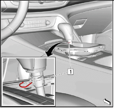
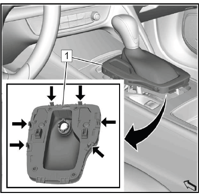
3.
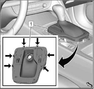
Gently release the transmission control lever boot bezel (1) at the front. Unclip 6 retainers (arrows), using a flat bladed tool.
4. Pull the transmission control lever boot bezel up to gain access to the electrical connector.
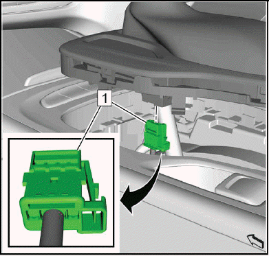
5.
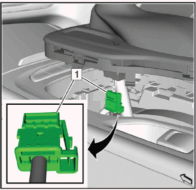
Electrical Connector (1) - Disconnect.
6.
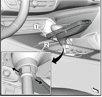
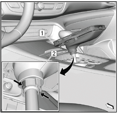
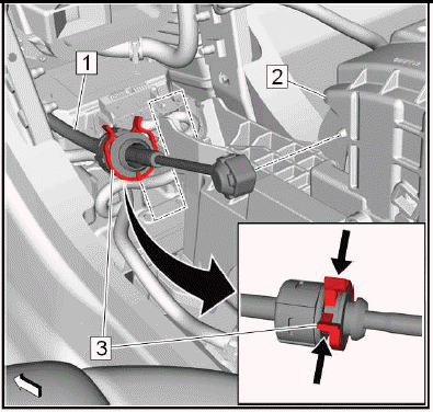
Pull the transmission control lever boot bezel (1) up to gain access to the transmission control lever boot retaining ring (2).
7. Release (arrows) the 2 latches of the transmission control lever boot retaining ring to separate the transmission control lever boot from the transmission control lever knob.
8. Push the transmission control lever boot bezel along with the retaining ring down to gain access to the transmission control lever knob fastener.
9.
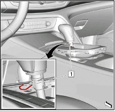
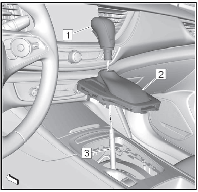
Transmission Control Lever Knob Fastener (1) - Remove.
10.
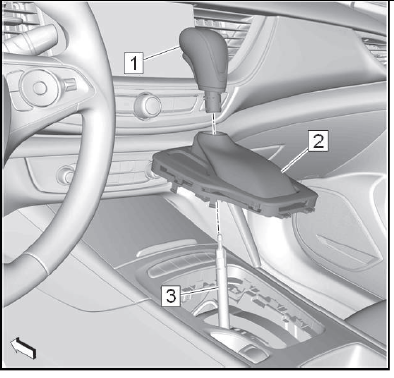
Transmission Control Lever Knob (1) @Transmission Control Lever (3) - Remove.
11. Transmission Control Lever Boot (2) @Transmission Control Lever - Remove.
Installation Procedure
1.
Transmission Control Lever Boot (2) @Transmission Control Lever (3) - Install.
2. Transmission Control Lever Knob (1) @Transmission Control Lever - Install.
3.
NOTE: Ensure the correct orientation of the transmission control lever knob fastener.
Transmission Control Lever Knob Fastener (1) - Install.
4. Check the transmission control lever knob for proper seat by pulling and twisting.
5.
Pull the transmission control lever boot bezel (1) along with the transmission control lever boot retaining ring (2) up.
6. Install the transmission control lever boot retaining ring to the transmission control lever knob. The 2 latches (arrows) of the transmission control lever boot retaining ring must engage noticeable.
7. Push the transmission control lever boot bezel down.
8.
Electrical Connector (1) - Connect.
9.
Install the transmission control lever boot bezel (1). First install the bezel at the rear then clip in the front of the bezel. Clip in 6 retainers (arrows).
10. Shift the transmission control lever into "P" position.
11. Release the parking brake.
TRANSMISSION CONTROL LEVER INSULATOR REPLACEMENT
Preliminary Procedures
1. Refer to Transmission Control Lever Knob Replacement.
2. Refer to Front Floor Console Replacement.
- Transmission Control Lever Insulator
TRANSMISSION CONTROL REPLACEMENT
Removal Procedure
1. Transmission Control Lever Knob - Remove - Refer to Transmission Control Lever Knob Replacement
2. Front Floor Console - Remove - Refer to Front Floor Console Replacement
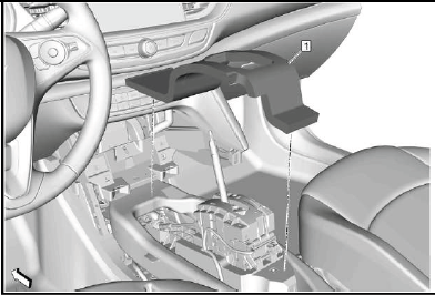
3.
Remove the transmission control lever insulator (1).
4. Front Floor Console Rear Air Front Duct - Remove - Refer to Front Floor Console Rear Air Duct Replacement (Front) Refer to Front Floor Console Rear Air Duct Replacement (Rear) 5.
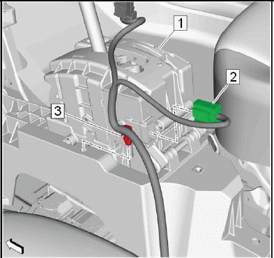
Range Selector Lever Cable (1) @Transmission Control (2) - Remove.
- Push (arrows) the 2 lashes of the retainer (3) to disengage the range selector lever cable from the front of the transmission control.
- Remove the range selector lever cable with a suitable tool from the ball joint of the transmission control.
6.
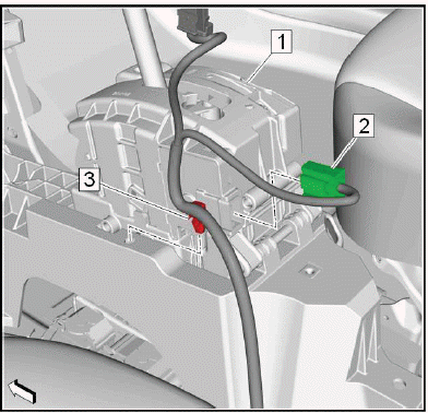
Wiring Harness Clip (3) @Transmission Control (1) - Unclip.
7. Electrical Connector (2) @Transmission Control - Disconnect.
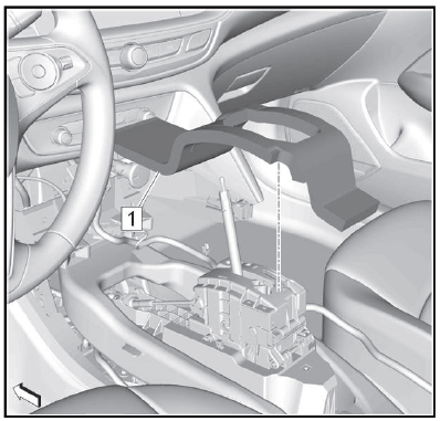
8.
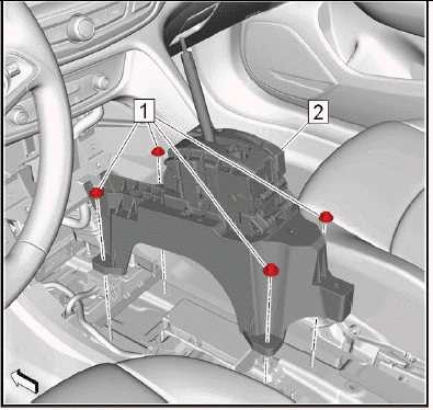
Transmission Control Nut (1) - Remove[4x].
9. Transmission Control (2) - Remove.
Installation Procedure
1.
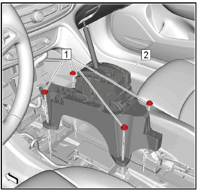
Transmission Control (1) - Install.
2. Transmission Control Nut (2) - Install and tighten[4x]9N.m (80 lb in).
3.
Electrical Connector (2) @Transmission Control (1) - Connect.
4. Wiring Harness Clip (3) @Transmission Control - Clip.
5.
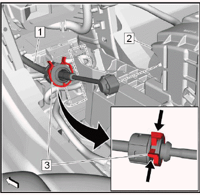
Range Selector Lever Cable (1) @Transmission Control (2) - Install.
- Install the range selector lever cable to the ball joint of the transmission control.
- Push the range selector lever cable to the front of the transmission control. The retainer (3) must engage noticeable.
6. Front Floor Console Rear Air Front Duct - Install - Refer to Front Floor Console Rear Air Duct Replacement (Front) Refer to Front Floor Console Rear Air Duct Replacement (Rear).
7.
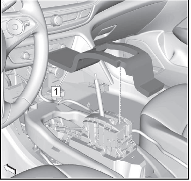
Install the transmission control lever insulator (1).
8. Front Floor Console - Install - Refer to Front Floor Console Replacement.
9. Transmission Control Lever Knob - Install - Refer to Transmission Control Lever Knob Replacement.
Adjustment Procedure
1. Range Selector Lever Cable - Adjust - Refer to Range Selector Lever Cable Adjustment.
TRANSMISSION FLUID DRAIN AND FILL
Draining Procedure
1. Raise and support the vehicle. Lifting and Jacking the Vehicle.
2.
Transmission Fluid Drain Plug (1) - Remove - Refer to Transmission Fluid Filler Overflow Tube and Drain Plug Removal.
3. Drain the transmission fluid into a suitable container.
4. Transmission Fluid Drain Plug - Install - Refer to Transmission Fluid Filler Overflow Tube and Drain Plug Installation.
5. Lower the vehicle.
Filling Procedure
1. Battery Tray - Remove - Refer to Battery Tray Replacement.
2.
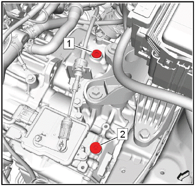
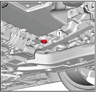
NOTE: The transmission oil filler plugs installed at locations 1 & 2 at the vehicle assembly plant are one-time-use. They have an interference fit and do not have O-rings. Once removed, these plugs must be replaced. The service part (replacement plug) available in the Electronic Parts Catalog (EPC) comes with an O-ring. Lubricate the seal with AW-1 fluid and install the O-ring prior to installing the plug. At each subsequent service, the service part plug (replacement plug) O-ring seal must be replaced. It is a one-time-use part. It is available separate from the plug in the EPC.
Remove a transmission oil filler plug (1) or (2), whichever is easier to access.
3. Fill the transmission to the proper level with the correct fluid. Approximate Fluid Capacities, and Adhesives, Fluids, Lubricants, and Sealers.
4. Install the transmission oil filler plug (1) or (2). Transmission Oil Filler Plug Replacement.
5. Battery Tray - Install - Refer to Battery Tray Replacement.
6. Raise the vehicle.
7. Check the transmission fluid level. Transmission Fluid Level and Condition Check.
8. Lower the vehicle.
9. Reset the learned values of the transmission control module. Learned Values Reset
TRANSMISSION OIL FILLER PLUG REPLACEMENT
Removal Procedure
1. Battery Tray - Remove - Refer to Battery Tray Replacement.
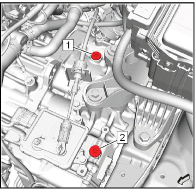
2.
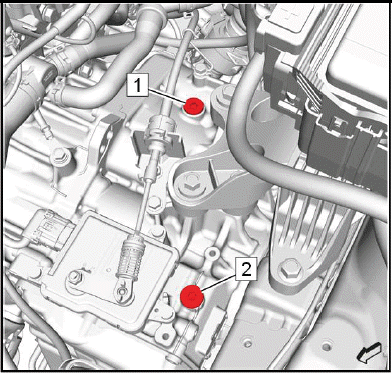
Remove a transmission oil filler plug (1) or (2).
Installation Procedure
1.
NOTE: The transmission oil filler plugs installed at locations 1 & 2 at the vehicle assembly plant are one-time-use. They have an interference fit and do not have O-rings. Once removed, these plugs must be replaced. The service part (replacement plug) available in the Electronic Parts Catalog (EPC) comes with an O-ring. Lubricate the seal with AW-1 fluid and install the O-ring prior to installing the plug. At each subsequent service, the service part plug (replacement plug) O-ring seal must be replaced. It is a one-time-use part. It is available separate from the plug in the EPC.
CAUTION: Refer to Component Fastener Tightening Caution.
Install the transmission oil filler plug (1) or (2) and tighten to 30N.m (22 lb ft).
2. Battery Tray - Install - Refer to Battery Tray Replacement.
READ NEXT:
 Vent Hose Replacement
Removal Procedure
1. Raise and support the vehicle. Lifting and Jacking the Vehicle.
2.
Transmission Vent Hose (1) @Transmission - Disconnect.
3. Lower the vehicle.
4.
Unclip the vent hose retain
Input Speed Sensor Replacement
Removal Procedure
1. Control Valve Body - Remove - Refer to Control Valve Body Replacement.
2.
Input Speed Sensor Bolt (1) - Remove.
3. Input Speed Sensor (2) - Remove.
Installation Procedure
1.
In
Front Wheel Drive Shaft Seal Replacement - Left Side
Special Tools
DT-446 Seal Installer
EN-45000 Seal Remover
Equivalent regional tools: Refer to Special Tools
Removal Procedure
1. Raise and support the vehicle.
2. Front Wheel Drive Half Shaft- Le
SEE MORE:
Hydraulic Brake Component Operation Visual Inspection
1.
WARNING: Refer to Brake Fluid Irritant Warning.
CAUTION: Refer to Brake Fluid Effects on Paint and Electrical Components
Caution.
With the tire and wheel assemblies removed and the brake rotors retained by
wheel lug nuts, visually
inspect the caliper piston dust boot (2) sealing area to ensure
DTC P0340, P0341, P0365, or P0366
Diagnostic Instructions
Perform the Diagnostic System Check prior to using this diagnostic
procedure: Diagnostic
System Check - Vehicle
Review the description of Strategy Based Diagnosis: Strategy Based
Diagnosis
An overview of each diagnostic category can be found here: Diagnostic
Proced
