Buick Regal: Specifications
FASTENER SPECIFICATIONS
Single Use Non-Threaded Fasteners/Components
Application
NOTE: All fasteners/components listed in this table MUST BE DISCARDED and replaced with NEW after removal.
Camshaft Cover Gasket
Combustion Fuel Injector Seal
Connecting Rod Bearing
Crankshaft Front Oil Seal
Crankshaft Rear Oil Seal
Cylinder Head Core Hole Plug
Cylinder Head Gasket
Engine Coolant Thermostat Gasket
Engine Oil Cooler Gasket
Exhaust Manifold Gasket
Fuel Injector Seal Ring
Fuel Injector Spacer
Fuel Pump Gasket
Fuel Pump Housing Seal
Intake Manifold Gasket
Oil Pump Screen Gasket
Oil Pump Seal
Piston Pin Retainer
Positive Crankcase Ventilation Hose Fitting
Positive Crankcase Ventilation Tube
Positive Crankcase Ventilation Valve
Thermostat Bypass Pipe Gasket
Throttle Body Gasket
Timing Chain Tensioner Gasket
Turbocharger Coolant Feed and Return Pipe Gasket
Turbocharger Coolant Feed and Return Pipe Washer
Turbocharger Gasket
Turbocharger Oil Feed Pipe Gasket
Turbocharger Oil Feed Pipe Washer
Turbocharger Oil Return Pipe Gasket
Vacuum Pump Gasket
Vacuum Pump Seal
Valve Stem Oil Seal
Water Outlet Gasket
Water Pump Gasket
Single Use Threaded Fastener/Component Tightening Specifications
NOTE: All fasteners/components listed in this table MUST BE DISCARDED and replaced with NEW after removal.
.png)
NOTE: All fasteners/components listed in this table MUST BE DISCARDED and replaced with NEW after removal.
.png)
Reusable Threaded Fastener Tightening Specifications
NOTE: All fasteners listed in this table can be reused after removal.
.png)
NOTE: All fasteners listed in this table can be reused after removal.
.png)
NOTE: All fasteners listed in this table can be reused after removal.
.png)
APPROXIMATE FLUID CAPACITIES
.png)
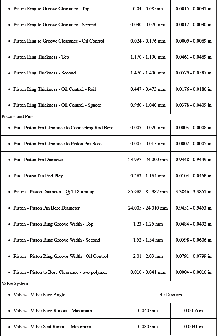
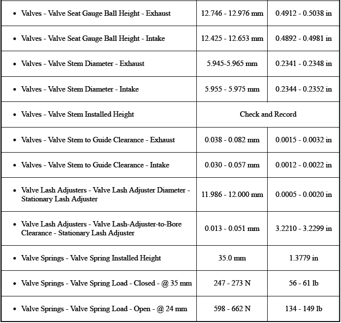
ENGINE MECHANICAL SPECIFICATIONS
.png)
.png)
.png)
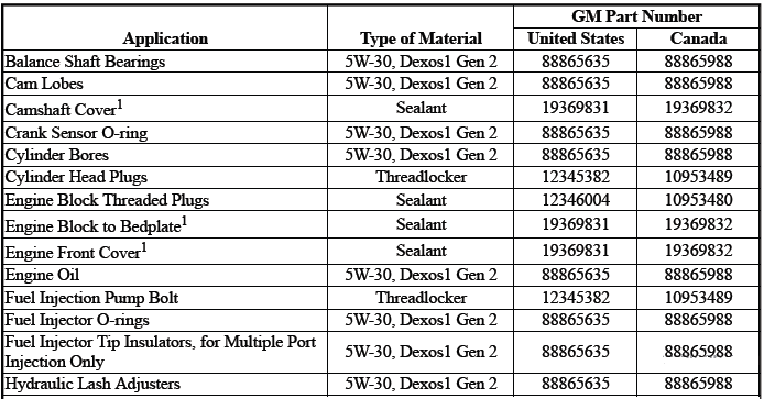
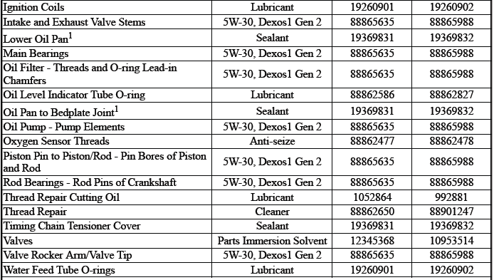
ADHESIVES, FLUIDS, LUBRICANTS, AND SEALERS
1 Ensure proper use of room temperature vulcanizing (RTV) sealant.
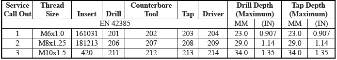
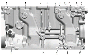
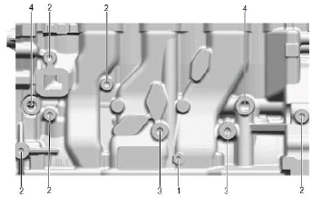
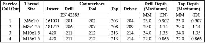
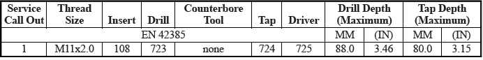
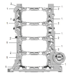
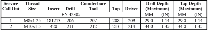
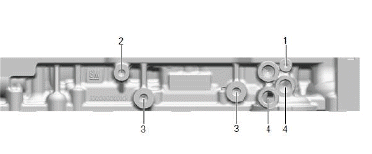
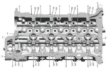
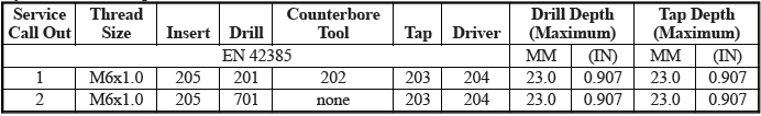
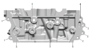
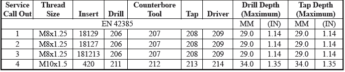
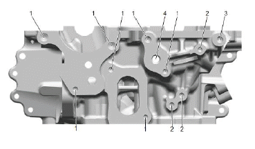
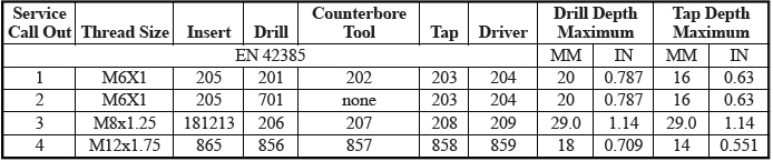
THREAD REPAIR SPECIFICATIONS
Engine Block - Front View
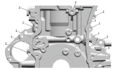
Engine Block - Front View
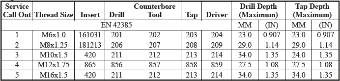
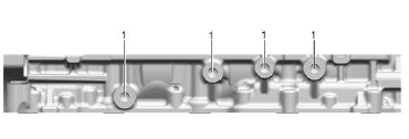
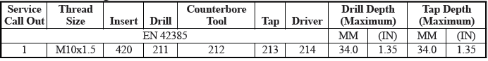
Engine Block - Back View
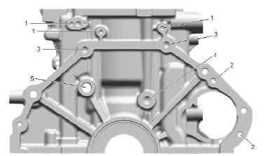
Engine Block - Back View
Engine Block - Right Side View
Engine Block - Right Side View
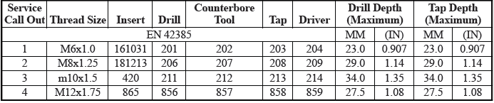
Engine Block - Bottom View
Engine Block - Bottom View
Engine Block - Left Side View
Engine Block - Left Side View
Engine Block - Top View
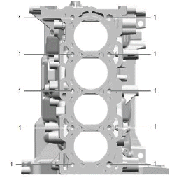
Engine Block - Top View
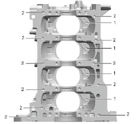
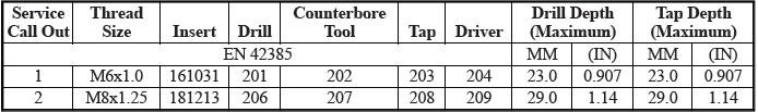
Lower Crankcase - Bottom View
Lower Crankcase - Bottom View
Lower Crankcase - Right Side View
Lower Crankcase - Right Side View
Lower Crankcase - Left Side View
Lower Crankcase - Left Side View
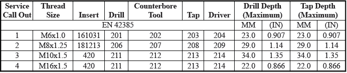
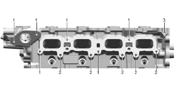
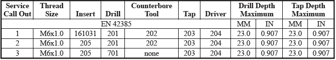
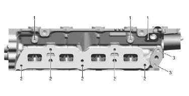
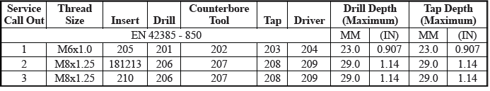
Cylinder Head - Top View
Cylinder Head - Top View
Cylinder Head Right Side View - Intake Manifold Deck Face
Cylinder Head Right Side View - Intake Manifold Deck Face
Cylinder Head Left Side View - Exhaust Manifold Deck Face
Cylinder Head Left Side View - Exhaust Manifold Deck Face
Cylinder Head - Front View
Cylinder Head - Front View
Cylinder Head - Back View
Cylinder Head - Back View
Upper Oil Pan - Top View
Upper Oil Pan - Top View
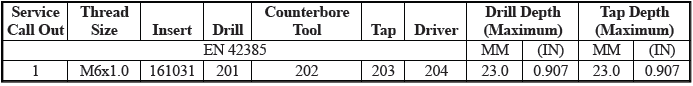
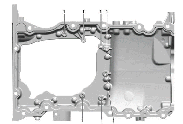
Upper Oil Pan - Bottom View
.png)
Upper Oil Pan - Bottom View
.png)
Upper Oil Pan - Front View
.png)
Upper Oil Pan - Front View
.png)
Upper Oil Pan - Back View
.png)
Upper Oil Pan - Back View
.png)
Engine Front Cover - Top View
.png)
Engine Front Cover - Top View
.png)
Engine Front Cover - Front View
.png)
Engine Front Cover - Front View
.png)
READ NEXT:
 Schematic Wiring Diagrams, Component Locator
Schematic Wiring Diagrams
ENGINE OIL LEVEL AND PRESSURE CONTROL SCHEMATIC WIRING DIAGRAM (LTG)
Component Locator
DISASSEMBLED VIEWS
Camshaft Cover and Components
Engine Coolant Air Bleed Pipe Bolt
DTC P06DA-P06DC
Diagnostic Instructions
Perform the Diagnostic System Check - Vehicle prior to using this
diagnostic procedure.
Review Strategy Based Diagnosis for an overview of the diagnostic
approach.
Diag
SEE MORE:
DTC B0083-B0088
Diagnostic Instructions
Perform the Diagnostic System Check - Vehicle prior to using this
diagnostic procedure.
Review Strategy Based Diagnosis for an overview of the diagnostic
approach.
Diagnostic Procedure Instructions provides an overview of each
diagnostic category.
DTC Descriptors
D
Radio/Audio System Description and Operation (IOS/IOT/IOU)
The entertainment system on this vehicle may have several different
configurations available to it. To determine the specific configuration of the
vehicle, please see the Service Parts ID Label, and refer to RPO Code List.
Each item in the list below represents topics covered in detail below.
D
